![]()
· Exit out of line creation by selecting the Select icon.
· Click in an empty part of the model to de-select the line.

The wireframe of the octagon is now complete.
The octagon can be quickly saved onto another level for use later.
![]()
· From the left side of the window, select the Levels button.

The levels form appears. This form is used mainly for the naming of levels and switching them on or off.
New names for levels are entered into the empty slots.
· In Level 5, enter the name Octagon and press the big X by the number 5.
![]()
![]()
![]() The
level is now displayed and a new button 5 has appeared on the left hand side,
indicating a new level has been named.
The
level is now displayed and a new button 5 has appeared on the left hand side,
indicating a new level has been named.
· Select Dismiss.
· Stretch a box over all of the lines. (They are all now selected/yellow)
· Move the cursor over the new level 5 button and click with the middle mouse.
The middle mouse will move the selected item into that level.
· Left mouse Click on level 5 button.
The left mouse will switch the level on or off. The Octagon disappears from the screen as the level is switched off. The model can now be saved.
· Select File è Save.
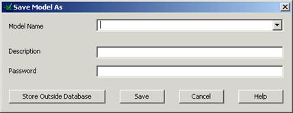
As a New Model was opened, PowerSHAPE has opened the File Save As form
· Enter the Model NameР as my-wireframe and press Save.
![]() The new name is displayed at the top.
The new name is displayed at the top.
 |
Arcs are generated on a plane, such as the XY. For better visualisation the view needs to be changed as well.
· Select a view down the Z-axis. ![]()
· Set the current plane to be Z. ![]()
· Select the Arc Menu. ![]()
·  Select the Full Arc option.

When this command is selected, the centre position of the circle is required. This can be input as a value or by snapping using the Interactive cursor.
![]()
· In the Command Input box enter 0 for the circle centre.

A preview of a circle has been generated with a radius based on the default value. The radius can be altered by dragging the indicated arrows to the required value.
![]()
To accept the circle, press select or another command.
· With the circle selected, click and hold the handles (arrows) and dynamically move the mouse to drag a new radius of 35.

The circle now has the correct radius. This method can be used to create the second circle at the same centre position, using the Intelligent cursor.
· Select the Circle command. ![]()
· Position the cursor over the centre of the first circle so the word Centre appears.
· Click the Left mouse button to position the centre of the new circle.
|
· Drag the second circle to a radius of 20mm.
The two basic circles are completed. Further circles are required for this model.
Hint: Use the command input box to enter the circle centre if it cannot be snapped.
· Create a circle at centre 100 –20 with a radius of 50mm
· Create a circle at centre 100 –20 with a radius to 35mm.
· Create a circle at centre 200 -40 with a radius of 20mm.
· Create a circle at centre 200 -40 with a radius of 10mm.
· ![]() Press Select.
Press Select.
The default option when creating tangent arcs is to trim back the associated geometry. In this case we do not wish to do this, so the flag (Trim tangent items) is switched off. This is found in the Options form under Tools at the top of the screen.
· Select Tools è Options, select Object then Arcs.

· Untick Trim Tangent items. ![]()
· Press Accept.
For the tangent arcs, the fitted arc option is the most suitable as it provides full dynamic control through all possible combinations.
Уважаемый посетитель!
Чтобы распечатать файл, скачайте его (в формате Word).
Ссылка на скачивание - внизу страницы.