![]()
![]()
![]()
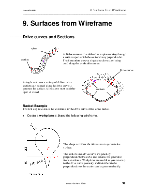
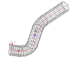
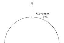
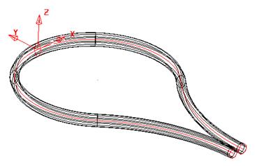
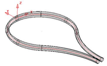
![]() A Drive curve can be defined as a spinerunning
through a surface upon which the sections hang perpendicular. The illustration
shows a single circular section being used along the whole drive curve.
A Drive curve can be defined as a spinerunning
through a surface upon which the sections hang perpendicular. The illustration
shows a single circular section being used along the whole drive curve.
![]()

![]()
![]()
|
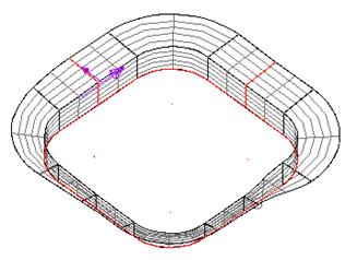
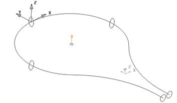
 A single section or a variety of
different size sections can be used along the drive curve to generate the
surface. All sections must be either open or closed.
A single section or a variety of
different size sections can be used along the drive curve to generate the
surface. All sections must be either open or closed.
The first step is to create the wireframe for the drive curve of the tennis racket.
· 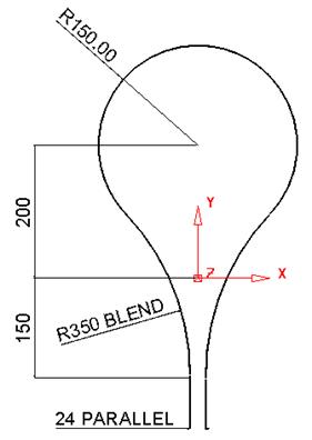 Create a workplane at 0 and
the following wireframe.
Create a workplane at 0 and
the following wireframe.
This shape will form the drive curve to generate the surface.
The sections on a drive curve are generally perpendicular to the curve and can also be generated from wireframe. Workplanes are useful as you can snap to the drive curve geometry and twist them to be perpendicular so the section can be generated easily.
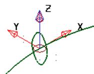
· Create a workplane and position it at the midpoint at the top of the racket.
· Zoom into the new workplane area
· Select the X principle plane. ![]()
· Generate three circles, circle 1 radius 8 at Z 0, circles 2 and 3, radius 4 at 0 0 10 and 0 0 –10.
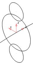
These will be filleted by an arc of radius 25. During this creation you may need to make another circle of radius 8, due to the automatic trimming.
· Fillet the circles with an arc of radius 25.
This will be the main centre section of the racket.
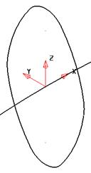
The other sections are circles and they can be placed directly at the grip end, without the need for another workplane.
![]()
· Select the Y principal plane.
· Generate two circles of radius 10 with their centres snapped to the end of the lines.
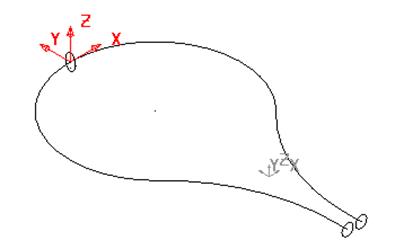
The drive curve and each cross section have to be turned into composite curves before a drive curve surface can be produced.
· Create a composite curve for each cross section and the drive curve.
· Deselect all and select all three sections
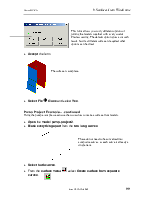
· ![]() From the surface menu
From the surface menu ![]() select
Create a drive curve surface.
select
Create a drive curve surface.
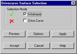
The Drive curve form appears.

This shows that you have some wireframe selected for the section/s for the surface.
· Click Drive Curve.
· Select the drive curve using the Left mouse button.
The drive curve will be displayed in Pink, and a Green tick will appear.
· Click Accept
This generates a surface with a changing section from a circle to the defined section and then back to the circle.
To maintain a particular section on the drive curve then extra sections need to be added.
· Select and Delete only the surface
· Select the top composite curve and select the Z principle
plane. ![]()
· From the Edit Toolbar, select Rotate object. ![]()
 A circle and arrow is drawn around the centre of the selected
object. This is the rotation centre and can be dragged to the required
position.
A circle and arrow is drawn around the centre of the selected
object. This is the rotation centre and can be dragged to the required
position.
Alternatively the option reposition the rotation option can be used which attached the arrow and circle to the cursor for positioning.
![]()
· Select reposition rotation axis
· Click on the centre of the racket.
· Select No. Copies as 1 and Angle as 90 and press return.
![]()
· Select No. Copies as 1 and Angle as 180 and press return.
![]()
Between these three shaped cross sections the surface shape will remain the same.
· Press Select. ![]()
· Generate a surface from drive curve using all five sections.
You can also use just one section; one of the circles, placed anywhere along the drive curve to generate a surface.
Note: If you have many composite curves to generate you can select all of the required geometry and select Edit èConvert è Wireframe to Composite Curve.
· Select Fileè Save As and enter my-racket.
· Select File è Close.
Using the pump example we can use the round and arc geometry to make a dome surface.
· Open the model pump-project2.
· Switch on all levels
· 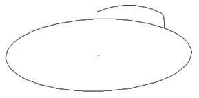
· Create two Composite Curves, the first to represent the Drive Curve and the second to represent the Section.
· Generate a Drive curve surface.
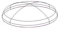
· Select and use the Right Mouse button menu to reverse the red surface.
· Unblank (Ctrl + L).
The ribs across are going to be created using Drive Curve Surfaces.
Уважаемый посетитель!
Чтобы распечатать файл, скачайте его (в формате Word).
Ссылка на скачивание - внизу страницы.