The section is scaled across corresponding points along the drive rails to generate the surface. Each drive rail need not necessarily contain the same number of points and they do not have to flow in the same direction from the defined section. Drive rail pairs can either be open or closed. The section can also be open or closed, however a closed section can only be used as long as the drive rails touch two distinct points on it. Both the section and the drive rails must be in the form of composite curves.
· Select File > Import, and then select the model two_rail_data.dgk from the area E:\users\training\PowerSHAPE_data\psmodels_n_dgk.
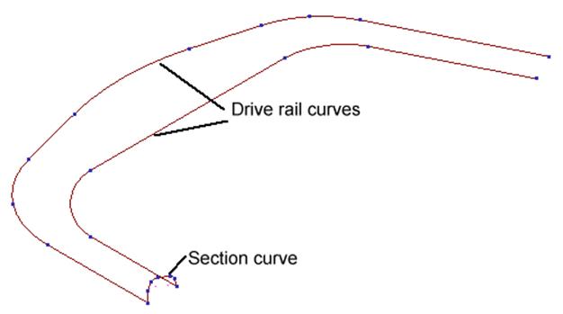
· Double click on one of the drive rail curves to bring up the curve toolbar.
· ![]() Shift-select the other composite curve.
Shift-select the other composite curve.
· Select the show point labels icon.
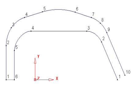
Each drive rail has a different number of points. Although a surface can be made from this, the distribution of the internal curves may not be desirable.
To fix this, even number of points and alignment need to be generated.
· ![]() Select the
top curve (10 points)
Select the
top curve (10 points)
· From the curve toolbar, select Create a point.
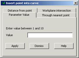
The insert point form appears. For this example the parameter value tab is used.
· Select the parameter tab and enter 5.5 and press Apply.
· Select Dismiss.
· Select the bottom curve (6 points)
· From the curve toolbar, select Reverse curve. ![]()
· ![]() From the curve toolbar, select Create
a point
From the curve toolbar, select Create
a point
· Select the parameter tab and enter 2.5 and press Apply.
· Enter 4.5 and press Apply.
· Enter 4.5 and press Apply.
· Enter 6.5 and press Apply.
· Enter 8.5 and press Apply.
· Select Dismiss. Select both curves.
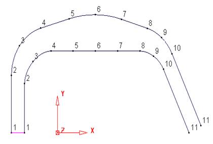
There are now the same number of points on each curve and they also align neatly.
· Select the section composite curve
· ![]() From the surface menu
From the surface menu ![]() select
Create surface from two rails.
select
Create surface from two rails.
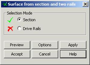
This form allows you to pick which composite curve is the section and which are the drive rails.
· Click the box Drive Rails and select both Drive rails curves.
· Press Preview.
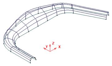
The surface shown left is previewed.
Note: The height has increased in proportion to the increased width of the original section.
· Select the Options tab from the form.
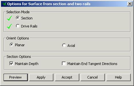
·  Tick the option to Maintain Depth and
Preview again.
Tick the option to Maintain Depth and
Preview again.
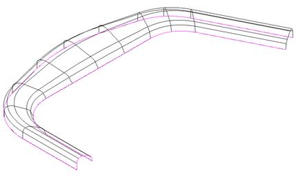
This time the height has been maintained to the original section.
· Select Accept.
· Select and Delete the surface.
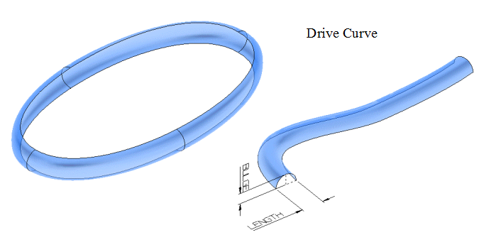
A Bead Surface is defined by specifying a Length and a Bulge across a drive curve. They can be used to quickly form decorative features on products or more functional features such as ‘Draw Beads’ on press tools.
This example creates a curve from the manually inputted points, which is then used to generate a bead surface.
· Select the point creation icon. ![]()
· Enter 4 points at the command input window.
-50 0 0
0 30 0
65 0 0
0 –30 0
· Press Select. ![]()
The four points can be snapped onto when creating a bezier curve.
· From the Curve Menu ![]() , select Create a
Bezier Curve
, select Create a
Bezier Curve ![]()
· Click each point in order and re-click the first point to close the curve.
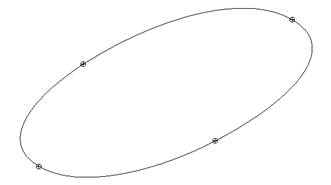

A closed bezier curve is produced.
· From the surface menu ![]() select Create a bead
surface.
select Create a bead
surface. ![]()
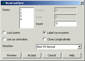
Each Point displayed in the Bead Surface form is relative to a position along the curve length. It is these positions that can then have Bulge and Length applied to them to create the surface.
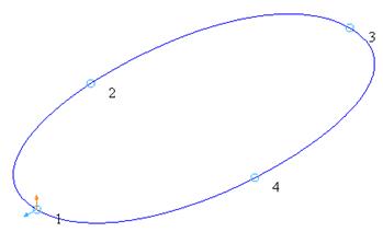
· Select Point 1 from the list and set Length 4 and Bulge 2.
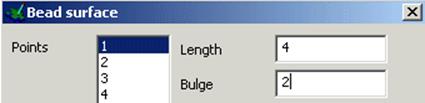
· Select Point 4 from the list and set Length 4 and Bulge 2.
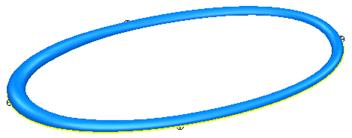
· Select Preview.
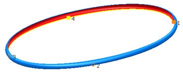
The surface is previewed with a Bead Length of 4 and Bulge of 2 through all points.
· Set the Direction to Radial and select Preview.
![]()
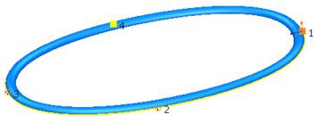
The surface is previewed with a radial form along the length of the curve.
Additional points can be inserted into the curve to modify the surface.
· Insert a point halfway between the existing points 2 and 3by entering 2.5 and pressing Return.
![]()
· 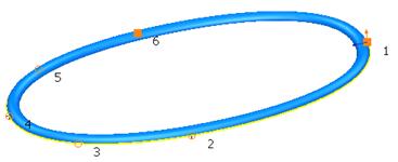 Insert a
point halfway between 4 and 5using a value of 4.5 and
pressing Return.
Insert a
point halfway between 4 and 5using a value of 4.5 and
pressing Return.
New points have been created along the curve and the curve renumbered.
Length and Bulge can be modified at these points.
· Delete any numbers on the Insert field to leave it blank.
· Select Point 3 from the list and set Length 5 and Bulge 3.
· Select Point 5 from the list and set Length 5 and Bulge 3.
· Select Point 4 from the list and set Length 6 and Bulge 4.
· Select Accept to create the surface.
The surface is created with a varying Bead form.
· Select File è Close and then Yes.
Уважаемый посетитель!
Чтобы распечатать файл, скачайте его (в формате Word).
Ссылка на скачивание - внизу страницы.