Workplanes are local datums, which are used to make working on a particular area of the model easier. The model can contain many workplanes, but only one can be active at a time. When a workplane is active that position is your X0 Y0 Z0 point. Workplanes are generated by selecting the origin and then aligning up the X, Y and Z axes accordingly.
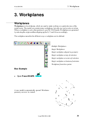
The workplane menu list the different ways a workplane can be defined.
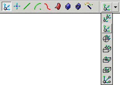
Multiple Workplanes
Single Workplanes
Single workplane aligned to geometry
Single workplane at top of selection
Single workplane at centre of selection
Single workplane at bottom of selection
Workplane from three points
· Open PowerSHAPE. 
A new model is automatically opened. Wireframe geometry can now be created.
· Select the Line menu. ![]()
· Select Rectangle option. ![]()
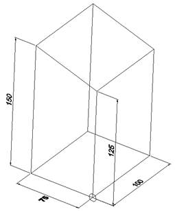
· Enter 0 in the Command input box and press Return.
· Enter 100 75 in the Command input box and press Return.
· Select the view Iso1. ![]()
· ![]() Select the Line menu.
Select the Line menu. ![]()
· From the down arrow, select Continuous Lines option.
· Move the mouse over the start point of the existing line (xyz 0) and click the left mouse button when End appears.
· Enter 0 0 125 in the Command input box and press Return.
· Enter 100 0 in the Command input box and press Return.
· Enter 0 0 -125 in the Command input box and press Return.
· ![]() Select the Line menu.
Select the Line menu. ![]()
· From the down arrow, select Continuous Lines option.
· Enter 0 75 in the Command input box and press Return.
· Enter 0 0 150 in the Command input box and press Return.
· Enter 100 0 in the Command input box and press Return.
· Enter 0 0 -150 in the Command input box and press Return.
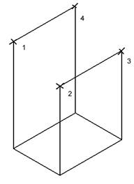
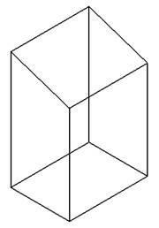
The main shape of the wireframe has been generated. Single lines can be generated by snapping to the numbered points to complete the design.
· Select the Line menu. ![]()
· Select Single Lines option. ![]()
· Snap onto points 1, 2 3 and then 4.
· ![]() Press Select.
Press Select.
The wireframe is complete.
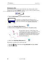
· Select the Workplane menu.![]()
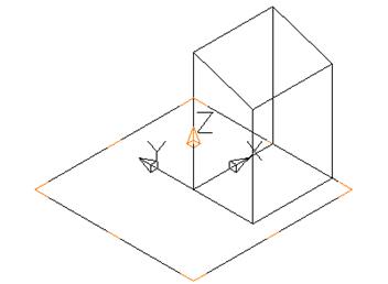
· Select Single Workplane. ![]()
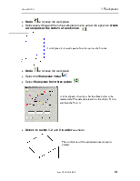
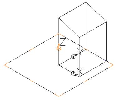
· Move the workplane cursor to the 0 position and click with the left mouse button.
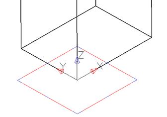
In this case a view of Iso 1 was selected, so that all of the three axes can be shown clearly.
The new workplane is positioned at the same position of the activated workplane. If no workplane is activated then it is positioned at the global or world co-ordinates. The workplane is automatically selected.
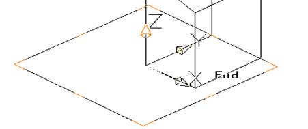
· Hold down the left mouse button over the large Y arrow and move the cursor around until it meets the End of the opposite line.
· Release the mouse button.
The centre position (origin) of the workplane remains at its current location but the X and Y axes are twisted around the Z so that the Y lies diagonal across the base of the wireframe.
This change will be undone. The position of the workplane will be changed.
· Select Undo ![]() .
.
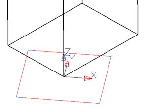
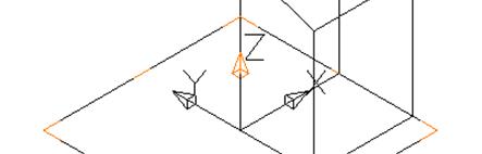
· Hold the left mouse button down over the centre of the workplane and drag the workplane to the other end of the vertical line.
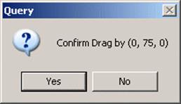
A confirm drag box appears detailing the distance from the previous point.
· Select Yes.
The workplane origin is now moved.
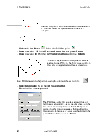
When selected, the Workplane borders contain yellow and blue lines. The yellow lines are used to control dynamic rotation about X or Y and the blue lines rotation about Z. Accurate alignment is achieved by dragging and snapping the coloured lines to key points on other entities.
The workplane can be rotated to align along the left face.
·  Hold down
the left mouse button ON the small blue
line just beyond the X arrow.
Hold down
the left mouse button ON the small blue
line just beyond the X arrow.
Note: for rotation about the Z Axis the blue lines also include the corners for quick alignment at 45 degrees.
· Drag the workplane blue line (rotating around the Z-axis) to line up as shown below.
The intelligent cursor will find end points of lines, mid points and other location as the mouse is moved. When a suitable position is found, releasing the mouse will fix the X-axis.
· Release the left mouse button. The X and Y axes are now modified.
![]()
 To
re-orientate the Y (and Z) axes without changing the X-axis one of the yellow
lines parallel to the X arrow is selected. The workplane is then dynamically
rotated around the X-axis the intelligent cursor being used to fix the
rotation.
To
re-orientate the Y (and Z) axes without changing the X-axis one of the yellow
lines parallel to the X arrow is selected. The workplane is then dynamically
rotated around the X-axis the intelligent cursor being used to fix the
rotation.
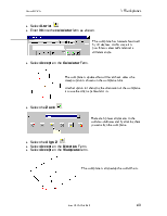
· Select one of the yellow lines beyond the Y arrow and drag the workplane to the top of vertical line (along Z) and release.
· Deselect the workplane by on a blank area of the screen.
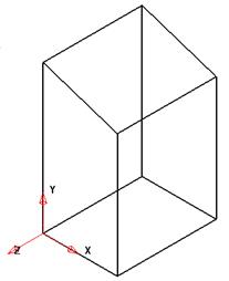
The workplane turns red (active) and is now the new 0 0 0 position.
The modified workplane being active is the dimensional datum until such time that it is deactivated or different workplane is activated.
· Select the Line menu. ![]() Select
Rectangle option.
Select
Rectangle option. ![]()
· Enter 20 20 in the Command input box and press Return.
· Enter 10 10 in the Command input box and press Return.
![]()
· Press Select.
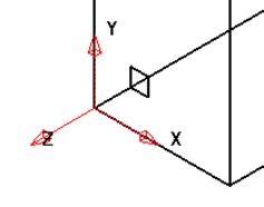
The new geometry is aligned along the left face.
The workplane can be altered by selecting it and double-clicking on it.
· Select the workplane with the left mouse button.
· Double click on the workplane.
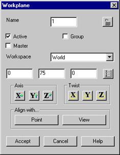
Within the Workplane Editing form direct values can be entered for position, rotation, etc. Tick boxes are available to Activate/De-activate or to nominate as the Master Workplane. When a workplane is Active it is displayed in red and is appears larger on the screen. When a workplane is de-actived it is displayed in grey and appears smaller in size. The Master workplane, if nominated is the default datum if another Workplane is deactivated.
Уважаемый посетитель!
Чтобы распечатать файл, скачайте его (в формате Word).
Ссылка на скачивание - внизу страницы.