· Select the Active button (so it becomes unticked) and then press Accept
·  Create a small square of side length 10,
starting at 20 20.
Create a small square of side length 10,
starting at 20 20.
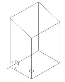
The second square appears relative to the world origin. If a workplane is deactived, then the datum of the model will default to world origin (unless a Master workplane has been specified).
· Box select everything on the screen (all the selected items turn yellow).
· ![]() From the workplane menu select the option to create
a workplane at the top of a selection.
From the workplane menu select the option to create
a workplane at the top of a selection.
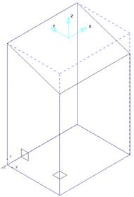
A workplane is created equal about the part at the top.
· Undo ![]() to remove the workplane.
to remove the workplane.
· ![]()
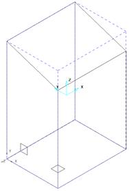 Select everything and from the workplane
menu select the option to create a workplane at the centre of a selection.
Select everything and from the workplane
menu select the option to create a workplane at the centre of a selection.
A workplane is created equal about the part at the centre.
· Undo ![]() to remove the workplane.
to remove the workplane.
· ![]() Select everything and from the workplane menu select
the option to create a workplane at the bottom of a selection.
Select everything and from the workplane menu select
the option to create a workplane at the bottom of a selection.
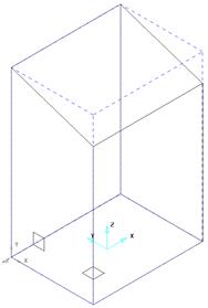
A workplane is created equal about the part at the bottom.
· Undo ![]() to remove the workplane.
to remove the workplane.
· Select the Workplane menu.![]()
· Select Workplane from three points. ![]()
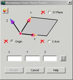
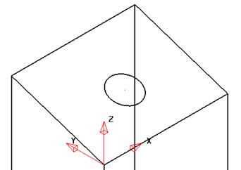
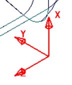
A form appears showing what the three points to be selected are. The default selection is the origin, X Axis and then the Y-Axis.
· 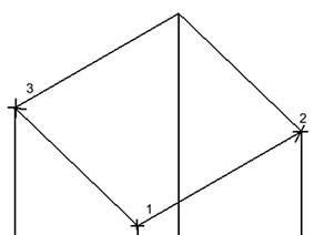 Select the points
1, 2 and 3 in order as shown.
Select the points
1, 2 and 3 in order as shown.
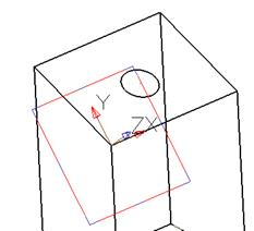
The workplane will be generated once Accept is picked.
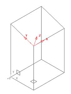
The new workplane is active and is called workplane number 2. The View menus will operate relative to the active workplane.
· Select the Arc Menu. ![]() Select the Full
Arc option.
Select the Full
Arc option. ![]()
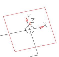
· Input the value r 12 in the Command input box andpress Return
· Input the value 50 35 in the Command input box andpress Return
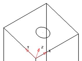
The circle is aligned with the workplane. As arcs are generated on the XY plane, the ability to use workplane allows arcs to be generated at different orientations.
Note: Workplanes can also be positioned using the options on the position form.
· Select workplane 2 with the left mouse button.
· Double click on workplane 2.
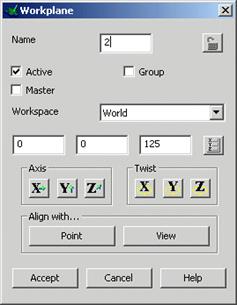
The Workplane editing form enables changes in rotation, realignment, repositioning, etc. As the form operates on the local datum it is not important whether the Workplane is Active or not but it must be selected. (For modifications relative to an alternative active datum use the options in the general Edit toolbar (Swiss Army Knife)).
· Select X-twist. ![]()
· Enter 30 into the calculator form as shown.
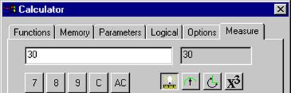
The workplane has rotated about itself by 30 degrees. At this stage it is possible to select AC and enter a different angle.
· Select Accept on the Calculator Form.
The workplane is updated but will revert back unless the Accept option is chosen on the workplane form.
Another option for changing the orientation of the workplane is to use the Align a particular Axis.
· Select the Z axis ![]() .
.
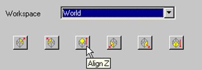
There are 6 preset alignments in the world co-ordinates and by clicking them you can align the workplane.
· Select the Align Z ![]() .
.
· Select Accept on the Direction Form.
· Select Accept on the Workplane form.
The workplane is aligned up the world Z-axis.
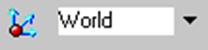
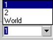
Below the graphics area in the bottom left hand corner is the workplane toolbar, which includes an icon for creating temporary workplanes as well as a table as an alternative means to control the naming and activation of workplanes.
 |
· Select the down arrow to select another workplane.
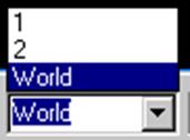
If workplane 1 is selected in the form it becomes active. A workplane can be renamed by clicking on the current name and typing over it with the new name followed by the return key.
![]()
· Click on the Temporary Workplane icon.
· Snap to some existing geometry (or anywhere in the graphics area).
The red and black temporary workplane appears. This workplane does not have access to a local editing form, but can be modified using the Edit toolbar options (Swiss Army Knife). It is automatically called Temporary and can be deleted from using the local menu or by pressing the Temporary Workplane icon.
![]()
· Click on the Temporary Workplane icon.
The Temporary workplane is removed from the model.
· Select File è Save. Enter the name my-workplanes and press Save.
· Select File è Close.
In a PowerSHAPE model you can designate a workplane as the Master Workplane. This master workplane is shown with thicker lines to distinguish it from the others.
If another active workplane is deactivated, instead of PowerSHAPE returning to the World co-ordinate system it activates the Master Workplane.
· Open the model golf_fin.
There are two Workplanes on this model called 1 and 2.These are situated above the World Co-ordinate system in the workplane menu.
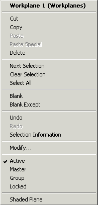
· Select Workplane 1 and click the right mouse button to bring up the menu.
· Select the option Master (this becomes ticked).
· Deselect the workplane to display the master status. (drawn in bold red)
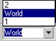
The workplane also appears below the World in the Workplane selector, so it is easy to find.
·  Activate workplane 2
and then deactivate it.
Activate workplane 2
and then deactivate it.
The master workplane becomes active, instead of the world origin. This is a must for users handling imported data in the car industry where traditionally every component part has a common datum (Car Line). This World datum could be metres away as well as being in an unsuitable orientation for tooling purposes. It must however be retained in case a copy of the data is to be returned to the supplier (in Car Line).
· Select File è Close.
Уважаемый посетитель!
Чтобы распечатать файл, скачайте его (в формате Word).
Ссылка на скачивание - внизу страницы.