§ Strategy 2: Rescheduling during the remaining interval from current time to the end of planning horizon with taking into account only remaining (not yet processed) works.
§ Strategy 3: Scheduling with initial manufacturing data during given planning horizon.
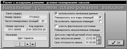
Fig.2. FOBOS-interface for assigning of Production scheduling strategy
Let J1, J2, J3 be values of integral deviation (penalty costs) between the previous shop-floor schedule and a schedule calculated via Strategies mentioned above. The economic advantages of the implementation of these Strategies for schedule correction call for a comparative evaluation of J1, J2 and J3. Denote Z = min(J1, J2, J3) the summarized minimal cost of a new shop-floor production schedule. After some canonical transformations of Ji (division by its maximal nonzero absolute value) analyzing the boundaries of cost-effective usage of Strategies 1, 2 and 3 we estimated the domains of their best implementation. Drawn in the plane (J1-J2, Z) they divide the area, described by the formula: Abs(J1-J2) < J1+J2 into five different zones (Figures 3 and 4). Thus each variant of production schedule is represented by FOBOS-DSS as a point in this plane: schedule correction Strategy is automatically chosen depending on what zone this point is located in.
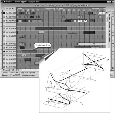
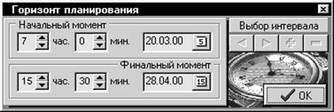
Fig.3. Production schedule and DSS Pareto set: calculation of domains of cost-effective usage of Scheduling strategies during planning period.
Moreover, the existence of alternative hysteresis-type zone (within the closed curve (m2,m3,m4,m5,m2) where DSS chooses the same Strategy that was implemented in the previous correction episode) is accounted for by the fact that the treated multicriterial problem is the problem of vector optimization with nonconvex criteria. The domains of the best usage depicted in Figures 3 and 4 are the projection of the corresponding Pareto set onto the plane (J1-J2, Z).
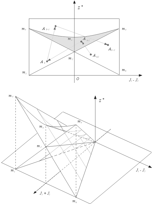
Fig.4. Topological structure of Domains as the "Swallow-tail" surface.
Finally, it must be noted that the marked boundaries also depend on the parameter J1+J2. Thus being constructed in the space (J1+J2, J1-J2, Z) they present a surface with topological structure equivalent to that of "Swallow-tail"-type bifurcational set (see Figure 4). Such a set is known to be structurally stable.
ВНЕДРЕНИЕ CAD/CAM СИСТЕМ В ПТО МП ОАО "АЛТАЙДИЗЕЛЬ"
Коростeлев Ю.И.,
гл. металлург ОАО "АЛТАЙДИЗЕЛЬ"
В рамках комплексного проекта “Создание интегрированного комплекса конструкторско-технологического проектирования на базе системы CAD/CAM/CAE CATIA и организация высокоэффективных автоматизированных технологий и производств на его основе” в проектно-технологическом отделе металлургического производства (ПТО МП) решаются следующие задачи:
- создание твердотельных моделей изделий/отливок/моделей отливок;
- автоматизация подготовки конструкторско - технологической документации;
- автоматизация подготовки ряда технологических процессов;
- автоматизация создания литейных моделей на основе LOM - технологий.
Для решения перечисленных задач в ПТО МП реализована информационная система, структура которой приведена на рис. 1.
Для создания твердотельных моделей используется программное обеспечение CATIA v4.20 компании DASSAULT, с использованием этого же программного обеспечения выполняется первоначальная подготовка конструкторско-технологической документации (на основе твердотельной модели создаются виды, сечения, разрезы, необходимые для документирования, которые затем сохраняются в отдельный файл формата DXF).
Дальнейшее оформление конструкторско-технологической документации выполняется на автоматизированных рабочих местах инженера-конструктора, на которых установлена сетевая версия CAD - системы T-Flex CAD 6.3 производства компании "Топ Системы".
Уважаемый посетитель!
Чтобы распечатать файл, скачайте его (в формате Word).
Ссылка на скачивание - внизу страницы.