Disassembly and Assembly 784C, 785C and 785C HAA Off-Highway Truck/Tractors Power Train. Transmission Planetary - Assemble, страница 4


View Image

https://sis.cat.com/sisfiles/g00/531/g00531417.jpg


Illustration 32

g00531417

  1. Install O-ring seal (175) and spring pin (176) to plug (173) .

View Image

https://sis.cat.com/sisfiles/g00/531/g00531422.jpg


Illustration 33

g00531422


View Image

https://sis.cat.com/sisfiles/g00/531/g00531395.jpg


Illustration 34

g00531395

  1. Use plug (173) in order to install tube assembly (174) to the bottom of the transfer case.

View Image

https://sis.cat.com/sisfiles/g00/531/g00531394.jpg


Illustration 35

g00531394

  1. Install two balls (172) into manifold assembly (142) .

View Image

https://sis.cat.com/sisfiles/g00/531/g00531390.jpg


Illustration 36

g00531390


View Image

https://sis.cat.com/sisfiles/g00/531/g00531389.jpg


Illustration 37

g00531389

------ WARNING! ------

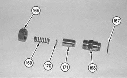
Personal injury can result from being struck by parts propelled by a released spring force.

Make sure to wear all necessary protective equipment.

Follow the recommended procedure and use all recommended tooling to release the spring force.

----------------------

  1. Install valve (171), washer (170) and spring (169) into body (168) .
  1. Install cap (166) and O-ring seal (167) onto body (168) .

View Image

https://sis.cat.com/sisfiles/g00/531/g00531386.jpg


Illustration 38

g00531386

  1. Install lubrication relief valve (164), two O-ring plugs (165) and the two O-ring seals into manifold assembly (142) .

View Image

https://sis.cat.com/sisfiles/g00/531/g00531383.jpg


Illustration 39

g00531383

  1. Install two dowels (163) to ring carrier assembly (144) .

View Image

https://sis.cat.com/sisfiles/g00/532/g00532357.gif


Illustration 40

g00532357

  1. Install Tooling (D) to manifold assembly (142). Attach Tooling (D) to a suitable lifting device and a hoist.
  1. Use Tooling (D) and the hoist to position manifold assembly (142) onto ring carrier assembly (144). The weight of manifold assembly (142) is 52 kg (115 lb).
  1. Use seven bolts (162) to install manifold assembly (142) to ring carrier assembly (144) .

View Image

https://sis.cat.com/sisfiles/g00/531/g00531375.jpg


Illustration 41

g00531375

  1. Install two seal rings (160) to ring carrier assembly (144) .
  1. Align the identification marks on seal adapter (159) with the identification marks on manifold assembly (142). Use seven bolts (161) to install seal adapter (159) onto manifold assembly (142) .

View Image

https://sis.cat.com/sisfiles/g00/532/g00532366.jpg


Illustration 42

g00532366

  1. Use Tooling (A) to install ball bearing (157) to clutch housing (145) .

View Image

https://sis.cat.com/sisfiles/g00/531/g00531368.jpg


Illustration 43

g00531368

  1. Install seal ring (158) into clutch housing (145) .

View Image

https://sis.cat.com/sisfiles/g00/531/g00531365.jpg


Illustration 44

g00531365

  1. Install Tooling (F) to clutch housing (145). Attach Tooling (F) to a suitable lifting device and a hoist.