|
|
|
|
View Image
|
|
|
|
|
|
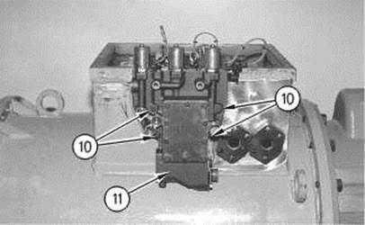
Illustration 128 |
g00533683 |
|
|
|
|
View Image
|
|
|
|
|
|
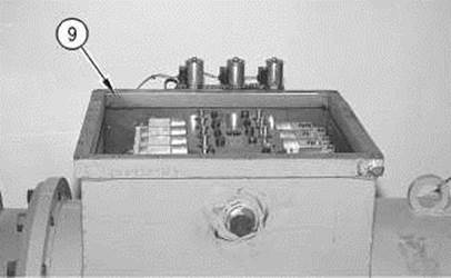
Illustration 129 |
g00530392 |
|
|
|
|
View Image
|
|
|
|
|
|
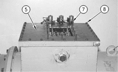
Illustration 130 |
g00530386 |
|
|
|
|
View Image
|
|
|
|
|
|
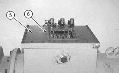
Illustration 131 |
g00530385 |
|
|
|
|
View Image
|
|
|
|
|
|
Illustration 132 |
g00530383 |
|
|
|
|
View Image
|
|
|
|
|
|
Illustration 133 |
g00530382 |
|
|
|
|
View Image
|
|
|
|
|
|
Illustration 134 |
g00530381 |
|
|
|
|
View Image
|
|
|
|
|
|
Illustration 135 |
g00530380 |
|
|
|
|
View Image
|
|
|
|
|
|
Illustration 136 |
g00530379 |
|
|
|
|
View Image
|
|
|
|
|
|
Illustration 137 |
g00530378 |
Конец формы
Начало формы
Конец формы
Начало формы
Конец формы
Начало формы
Конец формы
Уважаемый посетитель!
Чтобы распечатать файл, скачайте его (в формате Word).
Ссылка на скачивание - внизу страницы.