



Contents
3 Installing the Cabinet on the ESD Protection Floor 3-1
3.1 Positioning the Cabinet 3-2
3.1.1 Positioning an Independently Installed Cabinet 3-2
3.1.2 Positioning a Cabinet Close to Another One 3-3
3.1.3 Installation Check 3-4
3.2 Positioning the Support 3-5
3.2.1 Procedure 3-5
3.2.2 Installation Check 3-6
3.3 Installing the Support 3-7
3.3.1 Procedure 3-9
3.3.2 Installation Check 3-12
3.4 Installing the Cabinet on Support 3-13
3.4.1 Procedure 3-14
3.4.2 Installation Check 3-17
3.5 Installation Check Points 3-19
Figures
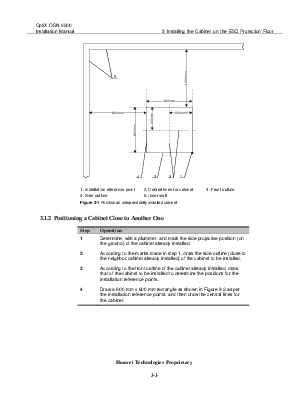
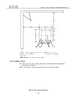
Figure 3-1 Position an independently installed cabinet 3-3
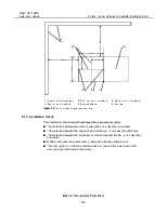
Figure 3-2 Position a cabinet close to another one 3-4
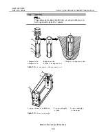
Figure 3-3 Support mounting holes for a single cabinet 3-6
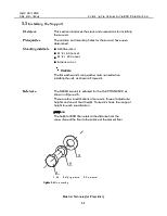
Figure 3-4 Bolt assembly 3-7
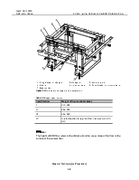
Figure 3-5 Outer view of the support and its accessories 3-8
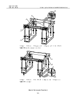
Figure 3-6 Install the expansion tube and expansion nut 3-10
Figure 3-7 Outer view of the support 3-10
Figure 3-8 Assemble the support to the slide rail 3-11
Figure 3-9 Fix the support 3-11
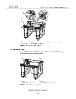
Figure 3-10 Install the fixing brackets for pallets 3-12
Figure 3-11 Expected result of installed support 3-12
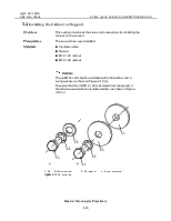
Figure 3-12 Bolt assembly 3-13
Figure 3-13 Demount feet of the cabinet 3-15
Figure 3-14 Level and secure the cabinet 3-16
Figure 3-15 Install the floor pallet 3-17
Figure 3-16 Expected result of installation on the ESD floor 3-18
Tables
Table 3-1 The contents of Chapter 3 3-1
Table 3-2 Support specifications 3-8
|
Overview |
This chapter introduces procedures and precautions for installing the cabinet on the ESD Protection floor. The OptiX OSN 9500 adopts the 600 mm deep European Telecommunications Standards Institute (ETSI) cabinet.
The cabinet is very heavy, so it shall be installed by over three persons. |
|
Contents |
Table 3-1 shows the contents of this chapter. |
Table 3-1 The contents of Chapter 3
|
Title |
Content |
|
3.1 Positioning the Cabinet |
Determines the position for cabinet in the equipment room. |
|
3.2 |
Determines the position for the support according to that for the cabinet. |
|
3.3 Installing the Support |
Introduces the relevant operations and procedures for installing the support. |
|
3.4 Installing the Cabinet on Support |
Introduces the relevant operations and procedures for installing the cabinet on the support. |
|
3.5 Installation Check Points |
Checks the cabinet installation to see whether the next step installation can be conducted. |
3.1 Positioning the Cabinet
|
Overview |
This section guides you in positioning the cabinet in the equipment room. The position where a cabinet will be installed varies with the number of cabinets and their layout. This section will introduce two positioning methods. n Position an independently installed cabinet. n Position a cabinet installed close to another one.
The cabinet shall be positioned accurately. For that purpose, read the construction-related technical documents before reading this section, to position the cabinet according to actual requirements. |
|
Prerequisites |
n The ETSI cabinet 600 mm deep and the accessories (including the support and fixing bracket) needed for cabinet installation have been transported to the project site. n The technical documents include a construction drawing that indicates where the cabinet will be installed. n In case there is no construction drawing due to some special reasons, the position can be determined according to the conditions on the site. |
Уважаемый посетитель!
Чтобы распечатать файл, скачайте его (в формате Word).
Ссылка на скачивание - внизу страницы.