

|
Master the processing procedures and methods of various common faults.
2.1 The Problems of Optical Power
OptiX BWS 320G system is composed of a large amount of optical components, and there are a large amount of fiber jumper jumpers inside the system and around the periphery. Fiber jumper is a vulnerable part. The damaged fiber jumper will directly cause the decrease of optical power. When optical power is decreased to a specific extent, bit errors might be generated in the equipment, or even cause the interruption of service. The causes of bit errors or service interruption may include the optical component being damaged.
2.1.1 Common Causes
(1) The transmission performance of fiber jumper is deteriorated for the external factors affecting.
(2) The optical modules in the accessed equipment are faulty.
(3) The performances of OptiX BWS 320G system optical components are deteriorated.
2.1.2 Common Methods
(1) Alarm and performance analyzing method.
(2) Instrument testing method.
(3) Substitution method.
2.1.3 Procedures
1. For equipment maintenance personnel
(1) If both the red and green indicators on a specific board are Off, but the other boards are in normal service, it indicates that the board is faulty. Then replace it. If no backup board is available for the board on-site, reset the board by plugging /unplugging it. Generally, the board can be put into operation and the normal service can be resumed. However, once the backup board is available, the faulty board should be replaced.
(2) If the green indicator of the board flashes quickly, feed back the problem to the NM maintenance personnel for sending configuration data again.
(3) If the red indicator of a specific board flashes three times every other second, the board might detect R-LOS alarm. Feed back the problem to NM maintenance personnel to confirm the alarm category.
(4) Cooperate with NM maintenance personnel to locate and process fault.
2. For NM maintenance personnel
Step 1: check whether the login to respective stations is normal and whether there is any critical alarm in respective stations.
(1) If a specific station can not be logged in, and a critical alarm is detected by the optical interface board of the adjacent sites, power failure might occur to this station or fault might occur in the optical fiber or monitoring channel board connected with this station.
(2) If there is no alarm on the optical path, while the login still fails, ECC channel might be blocked for such reasons as too heavy information traffic reported, etc. In this case, reset the SCC unit of the adjacent station.
Step 2: by the order of signal flow, check the optical power values of respective points in these related stations.
(1) Record the power values and compare them with the original data, so as to find the station with larger difference.
(2) Use an instrument to test the optical power of this point (note: it might affect other services).
Step 3: substitution method
(1) Replace the fiber jumper or board at the faulty point, till the normal optical power value is resumed.
2.1.4 Typical Example of Optical Power Decrease
1. Networking overview
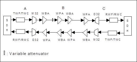
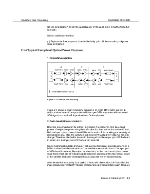
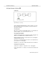
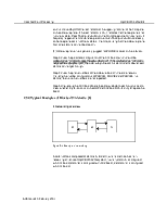
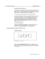
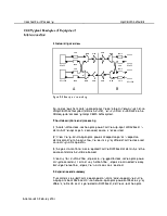
Figure 2-1 Example of networking
Figure 2-1 shows a chain networking diagram of an OptiX BWS 320G system, in which, stations A and C are provided with the open OTM equipment with accessed SDH signal, and station B is provided with OLA equipment.
2. Fault descriptions and solution
Bit errors are generated in the traffics from station A to station C. Test the optical powers of respective points along the traffic direction from station A to station C from NM, the input optical power of the WPA board in station B for receiving station A signal is decreased 4dB, while the output optical power of WBA board in station A has less change. Therefore, the fault is located in the range from the output port of WBA board in station A to the input port of WPA board in station B.
Since mechanical variable attenuator (with poor performance) is employed on site, it is first doubted that the attenuation of the variable attenuator in front of the input port of WPA board increases. Re-adjust the attenuator, so that the normal optical power value that is input into WPA board can be resumed, and record the input optical power of the variable attenuator (measured by optical power meter) simultaneously.
Уважаемый посетитель!
Чтобы распечатать файл, скачайте его (в формате Word).
Ссылка на скачивание - внизу страницы.