Since the service between stations B and C is normal, this fault will not be caused by optical path. Check the configuration of SC1 board in station C, the orderwire is configured to orderwire allowed through optical port. Therefore, this is not the problem of configuration.
Check the orderwire phone set of station C, the setting is proper.
When the orderwire phone number configurations of respective stations are checked, it is found that the second line of orderwire phone number in station A is the same as the first line of orderwire phone number in station C. After the first line of orderwire phone number in station C is changed to a different number which is not repeated with any other numbers on the network, stations A and B can call station C normally.
3. Experience and summary
Each OHP can be configured with three orderwire phone numbers. If the repeated numbers are configured, both numbers will not be called. In the above example, if stations B and C call the second number of station A (connect the orderwire phone set of station A to the second line of orderwire phone socket), it can not be gotten through as well.
2.4 Problem of Equipment Interconnection
The open OptiX BWS 320G system can access STM-64/16 or other optical signals. The accessed signal is transmitted transparently in OptiX BWS 320G system. If interconnection fails, it might be caused by the features of optical components.
2.4.1 Common Causes
(1) Optical fibers are connected in a wrong place. During maintenance, the most common cause is that optical ports are connected incorrectly.
(2) The problem of accessed equipment itself.
(3) The performances of TWF/TWC and RWF/RWC boards are deteriorated.
2.4.2 Common Methods
(1) Alarm and performance data analyzing method.
(2) Instrument testing method.
(3) Substitution method.
2.4.3 Procedures
Step 1: check whether fiber jumper is incorrectly connected according to the labels pasted previously. If yes, there might be no R-LOS alarm in equipment, but a large amount of abnormal performance values will be generated.
Step 2: use optical spectrum analyzer to analyze the quality of the output signal in OptiX BWS 320G system. The signal quality can be improved by increasing the output optical power of the corresponding wavelength conversion board at opposite end.
2.4.4 Typical Examples of Equipment Interconnection
1. Networking overview
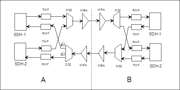
Figure 2-6 Example of networking
Figure 2-6 shows that a certain place employs the point-to-point networking structure of OptiX BWS 320G system (stations A and B), in which, SDH-1 and SDH-2 are the SDH equipment accessing to OptiX BWS 320G system.
2. Fault descriptions and processing
(1) A certain office measures the optical power from the output port of D32 board in station A. When optical path is recovered, service is not resumed.
(2) Check the input and output optical powers of respective points in respective stations according to the signal flow, the result is slightly different from the measured value during normal operation.
(3) A large amount of bit errors are reported from the RWF board of station A, and the services of stations A and B are blocked.
Since only No.1 and No.2 fiber jumpers are unplugged to measure the optical power during measurement, it is most likely that both fiber jumpers are connected inversely. Exchange the two fiber jumpers, then normal service is resumed.
3. Experience and summary
This accident is resulted from careless operation of maintenance personnel and no output port label of D32 board. Since the two output optical powers of D32 are slightly different, no R-LOS alarm is generated on RWF board, and the value of the optical power exported to the SDH equipment also has little change. SDH1 and SDH2 equipment do not generate R-LOS alarm, either. Therefore, the optical power of the entire optical path has little change, and it makes fault localization a little difficult.
Уважаемый посетитель!
Чтобы распечатать файл, скачайте его (в формате Word).
Ссылка на скачивание - внизу страницы.