Contents
4 Expansion and Upgrade 4-1
4.1 Equipment Expansion and Upgrade 4-1
4.1.1 Line Expansion and Upgrade 4-2
4.1.2 Ethernet Service Expansion and Upgrade 4-6
4.1.3 Cross-Connect Capacity Expansion and Upgrade 4-8
4.2 Network Expansion and Upgrade 4-10
4.2.1 On-line Increase of NE 4-10
4.3 Upgrade Unintelligent Network to Intelligent Network 4-13
Figures
Figure 4-1 Board configuration for line expansion of NE4 (mode 1) 4-3
Figure 4-2 Board configuration for line expansion of NE1 (mode 2) 4-5
Figure 4-3 Ethernet service expansion and upgrade of NE5 4-7
Figure 4-4 Add a node to a two-fiber bidirectional MS ring 4-10
Figure 4-5 The two-fiber bidirectional MS ring with NE6 added 4-12
Tables
Table 4-1 Three modes for line expansion 4-2
Table 4-2 Comparison between GXCH and EXCH 4-8
This chapter introduces the expansion and upgrade of the OptiX OSN 9500 in three parts:
n Equipment expansion and upgrade
n Network expansion and upgrade
n Upgrade from unintelligent network to intelligent network
4.1 Equipment Expansion and Upgrade
The equipment expansion and upgrade means to add boards and upgrade software to meet the requirement of services.
It is a shortcut to meet the requirement of increasing services and to maximize the utilization of operator’s investment.
The equipment to be expanded and upgraded should be configured based on the increasing service, transmission distance and other requirements. The OptiX OSN 9500 can be configured as MADM, so during the expansion and upgrade, the board should be added first and then is the subrack.
4.1.1 Line Expansion and Upgrade
![]() Caution:
Caution:
(1) The access capacity of IU slot varies with the cross-connect capacity.
(2) The increase of board should be within the limit of slot, access capacity or optical interface.
1. Case Description
Table 4-1 gives two modes for line expansion. The first mode is preferred because it is simpler and will not affect service.
Table 4-1 Three modes for line expansion
|
No. |
Condition |
Expansion mode |
Example |
|
Mode 1 |
The equipment provides enough slots for expansion, The line level needs to be upgraded and the optical interface needs to be added. |
Add boards. The operator needs to create a line on a station to expand TM or single ADM to multi-ADM. |
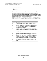
Figure 4-1 shows the line expansion of NE4. Add JL16 boards in slots IU19 and IU20 and add two STM-16 optical interfaces. |
|
Mode 2 |
The line capacity of a single station is not enough, the line level needs to be upgraded or the optical interface needs to be added. |
Replace the related line board with another board of higher rate, or has more optical interfaces. |
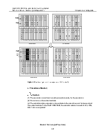
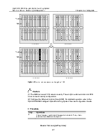
Figure 4-2 shows the line expansion of NE1. Replace the JL16 boards in slots IU04 & IU05 with JL64 boards. |
|
Mode 3 |
In initial stages, few optical interfaces are configured on the board that supports hot swapping of optical module. The expansion and upgrade can be achieved by adding optical modules. |
Add optical modules. |
For example, only eight optical interfaces are configured on JH41 in initial stages due to small traffic. With the increase of service, you can add optical modules on-site to expand the capacity of board. |
2. Procedure of Mode 1
|
Step |
Operations |
|
1 |
Check the working status of the expansion board and check whether the software is compliant. |
|
2 |
Use NM to check whether a slot is occupied and whether the slot to be inserted with board has capacity limit. |
|
3 |
Install the expansion board in the corresponding slot. |
|
4 |
Configure services, and configure overhead between optical interfaces of a ring network. |
|
5 |
Check whether NE works in normal status. |
Figure 4-1 Board configuration for line expansion of NE4 (mode 1)
3. Procedure of Mode 2
![]() Caution:
Caution:
(1) The upgrade may interrupt services, so carry out the operation during a period of small traffic under the guidance of technical engineer from Huawei.
(2) Only the boards that can be inserted in expansion slots can be upgraded.
(3) Upgrade the connected boards in adjacent NEs at the same time when upgrading line rate of a ring network. Otherwise, the upgrade may fail due to line rate mismatch.
(4) Before replace a board, always remove the fiber on it.
(5) Transient interruption of transmission equipment may result in fault in client side, so the maintenance personnel of the client side should cooperate with the operation.
Уважаемый посетитель!
Чтобы распечатать файл, скачайте его (в формате Word).
Ссылка на скачивание - внизу страницы.