Contents
3 Networking Application 3-1
3.1 Engineering Requirement 3-1
3.1.1 Project Overview 3-1
3.1.2 Service Requirement 3-3
3.1.3 Protection Requirement 3-4
3.1.4 Network Clock Requirement 3-4
3.1.5 Orderwire and ECC Requirements 3-4
3.2 Engineering Planning 3-5
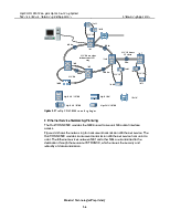
3.2.1 Networking Diagram 3-5
3.2.2 Protection Configuration 3-7
3.2.3 Hardware Configuration 3-8
3.2.4 Fiber Connection 3-16
3.2.5 Network Clock Tracing Diagram 3-17
3.2.6 Network Management and ID Allocation Diagram 3-17
3.2.7 Network Orderwire Diagram 3-18
Figures
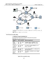
Figure 3-1 Geographic position of each node and optical cable distribution status 3-2
Figure 3-2 The OptiX OSN 9500 networking diagram 3-6
Figure 3-3 Ethernet transparent transmission service 3-7
Figure 3-4 Board configuration of NE1 3-9
Figure 3-5 Board configuration of NE2 3-11
Figure 3-6 Board configuration of NE3 3-13
Figure 3-7 Board configuration of NE4 3-14
Figure 3-8 Board configuration of NE5 3-15
Figure 3-9 Engineering information¾network clock tracing diagram 3-17
Figure 3-10 Network management and ID allocation diagram 3-18
Figure 3-11 Engineering information¾network orderwire diagram 3-19
Tables
Table 3-1 Service requirement of each node 3-1
Table 3-2 SDH service requirement of each node 3-3
Table 3-3 Ethernet service requirement of each node 3-3
Table 3-4 Equipment-level protection requirement 3-4
Table 3-5 Correspondence of place code and NE 3-5
Table 3-6 Equipment protection configuration 3-7
Table 3-7 Board configuration of NE1 3-8
Table 3-8 Board configuration of NE2 3-10
Table 3-9 Board configuration of NE3 3-12
Table 3-10 Board configuration of NE4 3-13
Table 3-11 Board configuration of NE5 3-15
Table 3-12 Fiber connection among NEs 3-16
Table 3-13 Fiber connection in NE3 and NE4 3-16
This chapter takes a networking example to illustrate the network planning of the OptiX OSN 9500 in terms of service, protection, orderwire, ECC and clock. It includes:
n Engineering requirement
n Engineering planning
3.1 Engineering Requirement
3.1.1 Project Overview
This project is to construct new lines among five stations (A, B, C, D and E) in a city. Table 3-1 shows the service requirement of each node.
Table 3-1 Service requirement of each node
|
Node |
A |
B |
C |
D |
E |
|
A |
- |
16 x STM-1 |
16 x STM-1(E) |
||
|
B |
- |
- |
8 x STM-4 |
||
|
C |
- |
- |
- |
16 x STM-1(E) |
|
|
D |
- |
- |
- |
- |
|
|
E |
- |
- |
- |
- |
- |
Уважаемый посетитель!
Чтобы распечатать файл, скачайте его (в формате Word).
Ссылка на скачивание - внизу страницы.