However, on a more complex model this would not always be the case so it is always advisable to use a spark gap of 0 in the Solid Core form then undersize the electrode in the machining package.
· Select Fileè Close and then Yes.
· Import the model toy_handle.psmodel from PowerSHAPE_data.
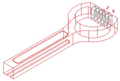
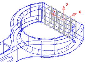
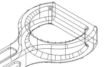
This model contains a large solid (main), made up of several commands and six separate solid ribs.
First of all the model requires fillets on all the main sharp edges.
· ![]() Double click on the Active Solid.
Double click on the Active Solid.
· From the Solids menu select Solid Fillet.
The Fillet main menu appears. The way this works, is that you select an edge of the solid and the path will be highlighted. The fillet path will only travel up to a sharp edge and stop. If follow continuous edges is switched on then the fillet can run around smooth corners, but not sharp.
It is generally good practise to fillet a solid by selecting edges that would remove sharp corners first. In the case of this model that would mean selecting the vertical edges first.
· Set a radius of 6 and select the 2 outer vertical edges shown.
 |

The fillet path runs until it finds a sharp edge.
· Select Apply.
· 
 Generate a radius 4 fillet along the top and bottom
faces.
Generate a radius 4 fillet along the top and bottom
faces.
The outer edge is now complete. The inner 'D' shape will be modified to include a fillet of radius 4mm flowing out to 6mm at the mid-point of the curved section.
·  Zoom into the 'D shape'
 |
· Fillet the vertical internal corners with a radius of 4mm.
· Select the top inner edge.
· Select theoption Advanced in the Fillet form.
This form allows you to select by mouse, an arc to represent the radius that the fillet will be at that point. By moving the mouse along the track, the word key will appear. Click at that point and a numbered arc is generated. This arc can be stretched or changed in the form to the desired radius.
· Select a View down the Z Axis.
· Click on the track to define locations for radius 4 and one place (arrowed) where radius 6 is required.
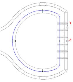
 radius
4
radius
4
![]()

 The dots show where suitable key points can be
clicked to initially input default arcs of radius 4.
· Modify the far left Arc Radius to 6 and press Accept.
The variable fillet is produced.
· Generate a similar variable fillet on the underside of the solid.
· Dismiss the fillet form.
![]() The
main fillets have been generated. The solid ribs can now be removed from the
main solid to produce a grip effect on the handle.
The
main fillets have been generated. The solid ribs can now be removed from the
main solid to produce a grip effect on the handle.
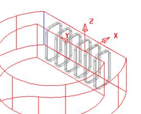
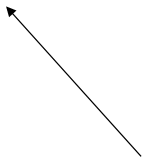
· Select all the solidribs and Remove from the Active solid.
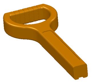
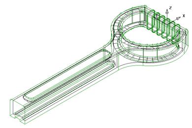
The completed model of the outer form is as shown left.
 In
this design the rib forms do not exist on the inner wall. As a result they can
be temporarily suppressed from the outer solid and the remaining inner form
created as a –3mm offset.
In
this design the rib forms do not exist on the inner wall. As a result they can
be temporarily suppressed from the outer solid and the remaining inner form
created as a –3mm offset.
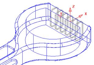
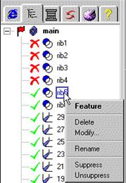
· In the Features Tree - Suppress all six ribs and the logo features from the main handle solid.
· Offset a copy of the selected solid by – 3mm to provide the inner wall, excluding the rib detail.
Now that the inner solid has been created the active, outer solidis updated to include the rib features again.
This is achieved by applying Unsuppress in Feature Tree to each rib in turn.
![]()
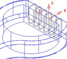
· With the outer solid active and the inner solid selected, select remove solid.
· Select Fileè Close and then Yes.
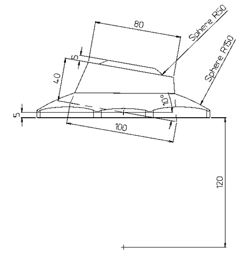
Generate the following shape.
 |
Уважаемый посетитель!
Чтобы распечатать файл, скачайте его (в формате Word).
Ссылка на скачивание - внизу страницы.