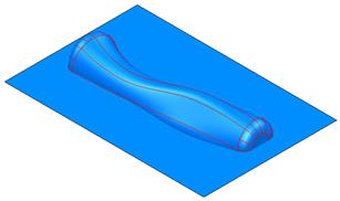
· Blank the cavity solid and switch on level 5.
· Select the Z principal plane.
· Create a surface primitive plane at 0, width 80, length 120.
This surface does not need to be turned into a solid for the split command.
· Make the handle solid Active
· Select the plane and from the
Features menu, select solid split ![]()
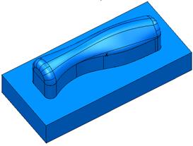
· Delete the upper half of the handle
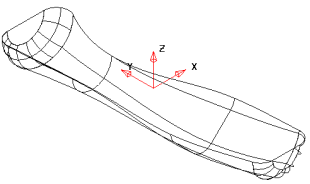
The solid has been split in half. If you shade the model you can see it more clearly.
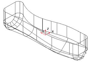
· Create a composite curve around the top edge of the handle.
· ![]() Open the Edits toolbar and
Project the curve to Z 0
Open the Edits toolbar and
Project the curve to Z 0 ![]()
· ![]() Make a solid extrusion 15mm up Z.
Make a solid extrusion 15mm up Z.
· Add the extrusion to the handle.
By projecting the curve onto Z0, it adjusts any tolerance errors when tracing the composite curve.
The extrusion can then be added
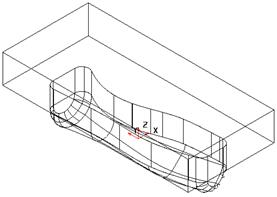
· Create a solid block at 0 0 15, length 60, width 130, height 20.
· ![]() Add the two solids together.
Add the two solids together.
· Rename the solid as Cavity_Electrode.
· Put the new solid, on level 5 and switch the level off.
A new insert can now be made.
· Select Unblank and Activate the Cavity solid.
· Select Principal Plane along Y.
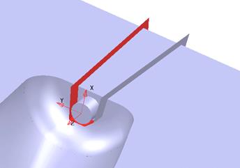
· Create a Solid Cylinder at 4.0 –52.0 -3.0 Radius 2.0 length 5.0
· Select the solid cylinder and Add
it to the active solid. ![]()
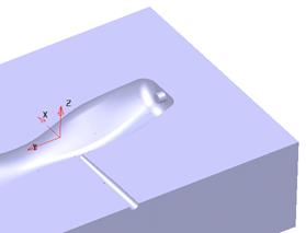
The solid now has an internal protrusion. A workplane is going to be created at the end of this protrusion to assist with the creation.
· ![]() Create a WorkPlane
between these 2 points
Create a WorkPlane
between these 2 points
Hint, create a line between the two points and then you can snap to the mid-point.
· ![]()
![]() Select Principal Plane along Z and Lock the
plane
Select Principal Plane along Z and Lock the
plane
![]()
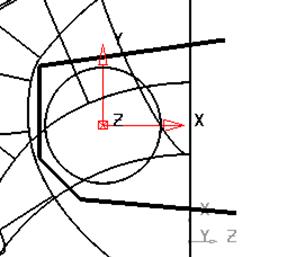
· Select a view down the Z axis
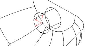
·  Sketch the shape of the loose piece or slide around the cylinder
as shown.
Sketch the shape of the loose piece or slide around the cylinder
as shown.
· Make a composite curve from the lines.
![]()
· ![]()
![]() Unlock the plane
Unlock the plane
![]()
· Select the wireframe and create a Solid Extrusion.
· Double click over the solid extrusion
· Enter a Negative length of 30, Draft angle 2 and Length 0
· Select Accept
The extrusion is the right size and shape.
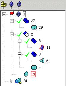
· Make sure the main Die insert solid is the active solid.
· In the Feature Tree area expand all the +symbols so the full history of the active solid can be seen working from the bottom upwards
· Select the solid extrusion
and Split active with selected solid. ![]()
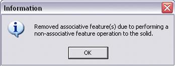
This is a warning to let you know that any associative features will be removed (the history will be lost).
· Click OK
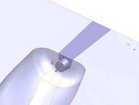
Most solid operations are associative so the Solid history can be kept and updated but this particular operation divides the solid into 2 separate entities as shown.
The History has been lost for the Die insert so it might be useful to undo this operation and create a copy of the original solid for reference/modification purposes.
· Open a new model
· Create a workplane at 0 and rename it Datum.
·  Generate a rectangle from -125
–150 with a size of X 250, Y 300.
Generate a rectangle from -125
–150 with a size of X 250, Y 300.
· Change the rectangle into a composite curve.
· Generate a solid extrusion up the Z-axis using the Solid extrusion icon.
· Change the extrusion length to 130 and Draft Angle to 340 and Accept.
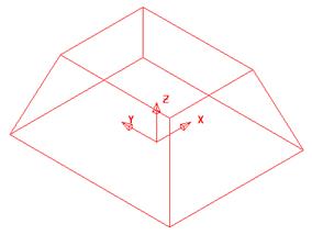
This has formed the basic shape of the Alarm Box.
The features can now be added.
· Generate a rectangle from -60 –80 130 with a size of X 120, Y 160.
Уважаемый посетитель!
Чтобы распечатать файл, скачайте его (в формате Word).
Ссылка на скачивание - внизу страницы.