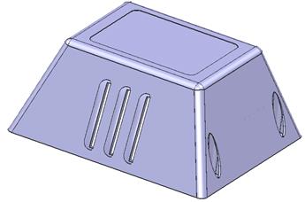
The ventilation holes are cut out of the solid.
 A
workplane is going to be made along the end face. New geometry can then be
constructed.
A
workplane is going to be made along the end face. New geometry can then be
constructed.
· Select Workplane Aligned to Geometry ![]() and select this face.
and select this face.
· Double-click the workplane and change workspace to be 0 –135 65.
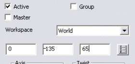
This will accurately position the origin as the angle has been set by selecting the solid face.
New wireframe will now be generated.
· Set the principal plane to Z.
· Generate a circle of radius 30 at the workplane (0) and create a solid extrusion
· Change the Lengthto 40 with a negative length of 20.
· Accept and Make it Active.
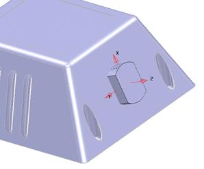
·  Generate a solid
block primitive at the 0 0 –20 Length 100 width 40 Height
30
Generate a solid
block primitive at the 0 0 –20 Length 100 width 40 Height
30
 |
![]()
· Select Intersect the Selected Solid.
· Select the main casing solid and make it Active.
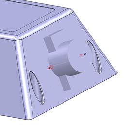
· With the Intersected Solid selected, select the solid boss icon.

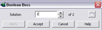
· Accept the outside solution.
The solid boss form offers 2 possible solutions (shown in white). It allows the Intersected feature to exist either on the outside face or the inside of the main casing
Although the boss is shown, it is now too big it can be sliced off using a surface. The surface must be facing the correct way to get the desired result.
· Create a Primitive surface Plane and position it at 0.
· ![]() Change width and height to 100. Reverse
the surface. (red side facing out)
Change width and height to 100. Reverse
the surface. (red side facing out)
· Select remove the selected surface/solid.
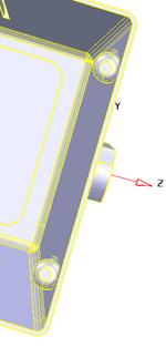
The boss has been trimmed back. A hole needs to be generated in this feature.
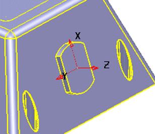
· Select from the features menu, create a hole. ![]()
· Position the hole at 0
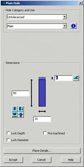

· Select Untoleranced
· Select Plain
·  Enter 16 and Accept
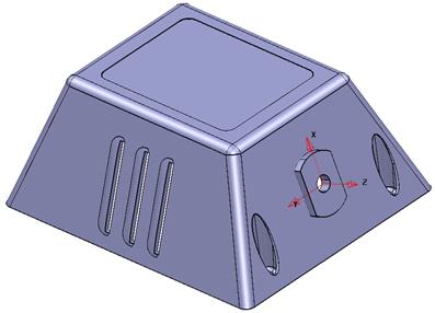
A hole is produced through the main solid.
There is also a solid boss and solid cut command. This command uses closed composite curves or single geometry with the active solid to either add an extruded boss to the solid or remove an extruded hole from the solid.
· Open a New Model and generate a workplane at 0.
· Generate a solid block primitive at 0 with dimensions, X 50, Y50 and Z 20.
· Generate a circle at 0 0 20 with a radius of 15.
· With the circle selected, select the solid boss icon.
· Select Fixed a Height of 20 and tick Reverse and press Accept.
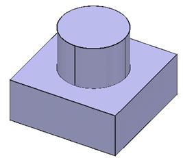
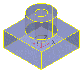
The solid boss is now joined to the solid block making a new solid.
A hole will be put in the top.
· Select Solid hole. ![]()
·  Select the top face
of the Solid
Select the top face
of the Solid
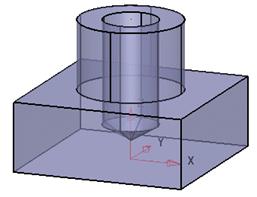
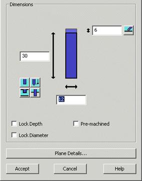
· Select an Untoleranced, Plain hole, with values as shown.
· Select Plane Details.

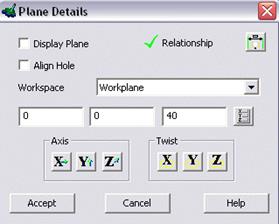
· ![]() Make X and Y 0.
Make X and Y 0.
· Press Accept.
· Press Accept.
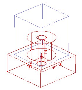
The hole is made. A solid core will now be generated.
· Select a view down Z.
· Create a Rectangle starting at –20 –20 65 and finishing at 40 40. Turn the square into a composite curve.
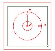
This defines the body of the electrode, which for successful operation must be completely within the component area as viewed down Z.
![]()
· Select the composite curve.
· From the solids menu, select solid core.
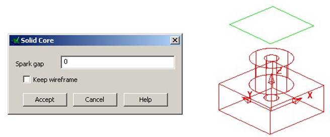
· Enter a spark gap of 0 and Accept the form.
The electrode is produced with a spark gap of 0 mm.
On simple models such as this entering a spark gap larger than 0 will probably give a satisfactory result i.e an electrode with an undersize.
Уважаемый посетитель!
Чтобы распечатать файл, скачайте его (в формате Word).
Ссылка на скачивание - внизу страницы.