Solids can be created as Primitives, from Wireframe and as the result of a Solid operation on another solid. Solids can also be generated from a group of surfaces that join together. PowerSHAPE is a Hybrid modeller so you can convert surfaces into solids and back again when required.
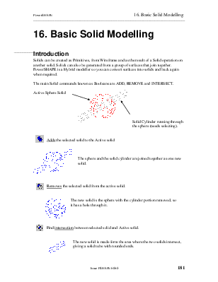
The main Solid commands known as Booleans are ADD, REMOVE and INTERSECT.
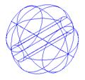
![]() Active
Sphere Solid
Active
Sphere Solid

Solid Cylinder running through the sphere (needs selecting).
![]()
Adds the selected solid to the Active solid
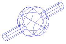
The sphere and the solid cylinder are joined together as one new solid.
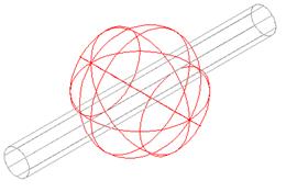
![]()
Removes the selected solid from the active solid.
The new solid is the sphere with the cylinder portion removed, so
it has a hole through it.
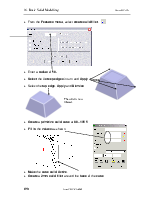
![]()
Find intersection between selected solid and Active solid.
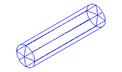
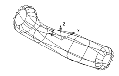
The new solid is made form the area where the two solids intersect, giving a solid tube with rounded ends.
The following Die example shows the application of solids to produce complex parts quickly and easily.
· Open a new model.
· Create a workplane at 0 and set the principal plane to Z.
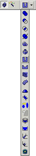
· ![]() Select the Solid
icon from the top toolbar.
Select the Solid
icon from the top toolbar.
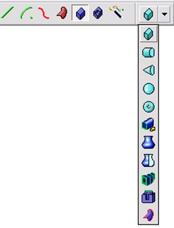
![]() Use the pull down arrow.
Use the pull down arrow.
· ![]() Select the Create
Solid Block icon
Select the Create
Solid Block icon
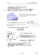
· Position the block by typing 0 0 -40
· Press ESC on the keyboard to break out of the command.
· Double click on the solid block in the graphics area which brings up the form below
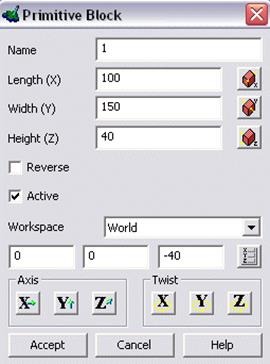
· Set the length as 100, width as 150 and height as 40 and press Accept.
 |

PowerSHAPE also displays a History tree of all the solid operations.
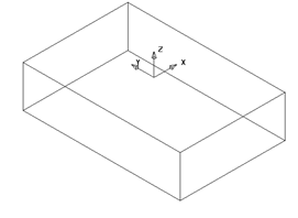
The first solid automatically becomes Active and is shown in Black.
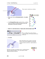
· ![]() Set the principal plane to X.
Set the principal plane to X.
· From the solid menu, select create solid cylinder
· Position the cylinder with the co-ordinates: -55 0 0
· Enter a radius of 2 and a length of 20.
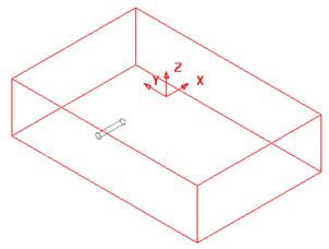
Further solids are shown in Grey, as only one solid can be Active at any time.
![]()
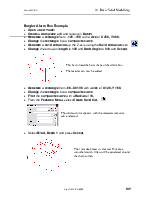
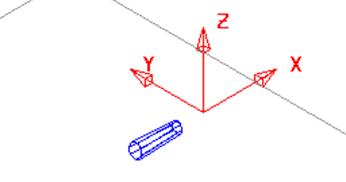
· Create a solid cone with the co-ordinates: -35 0 0.
· Enter a base radius of 2, a top radius of 1 and a length of 30.
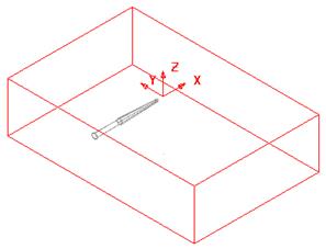
This model contains one active block and 2 non-active solids
 These
non-active solids need to be joined together to generate a new solid.
These
non-active solids need to be joined together to generate a new solid.
 |
|||
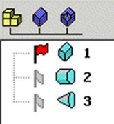
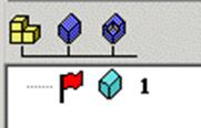
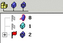
The feature tree now contains 3 solids. The active solid has a flying red flag to indicate that it is active.
· Select the solid cylinder and Right click over it to bring up the sub-menu and select Active.
· Select the other solid cone.
· From the Features menu ![]() , select Add the Selected Solid to
the Active Solid.
, select Add the Selected Solid to
the Active Solid. ![]()
The cylinder and cone will be automatically joined together as a new active solid.
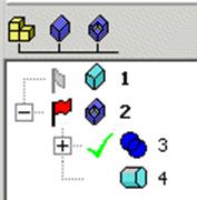
In the features tree, the second solid has become the active one and it shows that solid 3 has been added to the solid. This solid can be removed from the active solid by clicking on the tick. The solid can be added in again by selecting the cross.
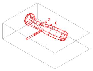
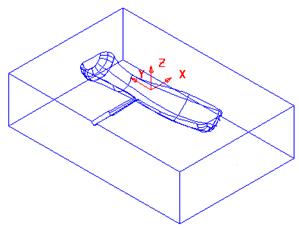
The component to go into the die will be imported as surfaces and then turned into a solid.
· Blank all of the solids and import the model handle.dgk from PowerSHAPE_data/psmodels_n_dgk.
The model is made up of various surfaces, which will be turned into a single solid.
· Select all surfaces.
· From the Solids menu, select Solid from Surfaces. ![]()
· Select Unblank.
The surfaces have become one single solid. If the surfaces do not match a watertight wizard will appear to fix any gaps.
A copy of this solid should be made for later use.
· Name level 5 as Solids, and leave the level switched off.
· Select the handle solid 8 and select the copy and then paste
· Put the pasted copy (already selected) it onto level 5.
This new solid can now be added to the original solids.
· ![]() With the ‘gate' solid 2 Active, select the
handle solid.
With the ‘gate' solid 2 Active, select the
handle solid.
· From the Features menu, select Create Solid Intersection.
PowerSHAPE has found the intersection between the two solids and has produced a new solid.
This is not required, as an addition would give the desired result. Using undo will return the model back to the original solids.
· ![]() Select Undo
Select Undo
· Add the two solids together using solid add.
To produce the cavity in the die block, this final solid can be subtracted from the die block. .
· ![]() Make the block solid active and select
the newly added solid.
Make the block solid active and select
the newly added solid.
· From the Features Menu, select Remove the selected Solid from the Active Solid.
A single solid is produced. As we already made a copy of the model before extracting from the block, the copy can be used to make a simple electrode, with no spark gap.
Уважаемый посетитель!
Чтобы распечатать файл, скачайте его (в формате Word).
Ссылка на скачивание - внизу страницы.