· Change the rectangle into a composite curve.
· ![]() Fillet the composite curve with a
Radius of 10.
Fillet the composite curve with a
Radius of 10.
· From the Features Menu, select Create Solid Cut.
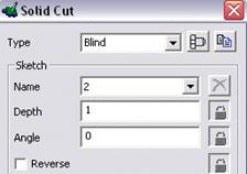
The solid cut form appears, with the selected composite curve selected.
· Select Blind, Depth 1 and press Accept.
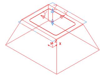
The 1mm deep recess is created. To make a smoother design, fillets will be generated around the sharp corners.
![]()
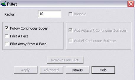
· From the Features menu, select create solid fillet.
 |
|||
· Enter a radius of 10.
· 

![]() Select the 4 steep edges in turn and Apply
Select the 4 steep edges in turn and Apply
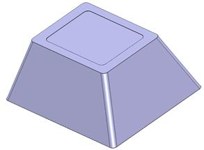
· Select the top edge. Apply and Dismiss
![]()
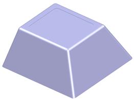
The solid is now filleted.
· 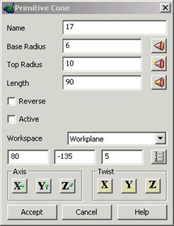 Create a primitive
solid cone at 80 –135 5
Create a primitive
solid cone at 80 –135 5
· Fill in the values as shown.
 |
· Make the cone solid Active.
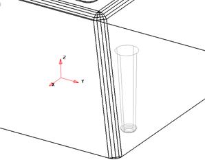
· Create a 2mm solid fillet around the base of the cone
· Mirror this solid around the YZ, XZ and YZ to produce a total of 4 cones
![]()
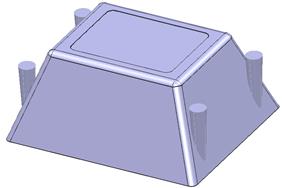
· Make the base unit solid Active.
· Select the 4 cones and Remove selected Solid from Active.
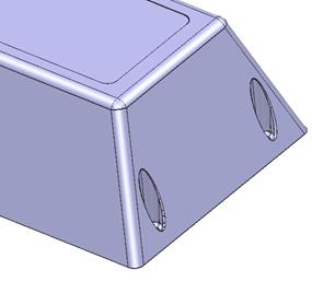
· ![]() Create a 1mm solid radius fillet around the top edge of each
cone
Create a 1mm solid radius fillet around the top edge of each
cone
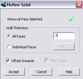
· ![]() Select Create a Hollow Solid.
Select Create a Hollow Solid.
 Hint:
to pick a side of a solid, it is better to use a shaded model and select in the
middle of the face.
Hint:
to pick a side of a solid, it is better to use a shaded model and select in the
middle of the face.
· ![]() Select the bottom
face of the model. The red cross will then change to a green tick
Select the bottom
face of the model. The red cross will then change to a green tick
 |
· Enter a Thickness of 3
· Press Accept.
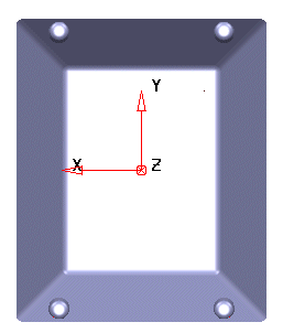
The solid now has a wall thickness with the middle portion removed as this view down –Z shows.
The next part is to design the vents.
· Select a view down the X axis and set the principal plane to X
· Create Rectangle at 0 -7 12 to 0 14 88
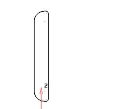
· Fillet the 2 left corners radius10.
· Fillet the 2 right corners radius 2.
· Create a composite curve of the profile.
· Select the solid and the profile
and from the curve menu select curve projection ![]()
· Select Along Principal Axis and press Accept
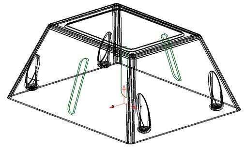

![]() The curve has
been projected through the entire solid in the direction of the Principal
plane.
The curve has
been projected through the entire solid in the direction of the Principal
plane.
Only the curves on the outside face are required.
· Delete the 2 curves on the inner face.
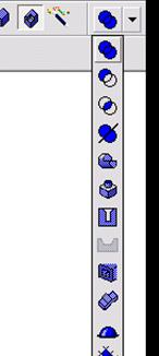
·  Select an
outside curve and then select Solid bulge
Select an
outside curve and then select Solid bulge
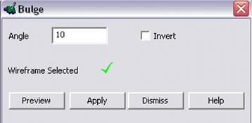
· Enter an Angle of 10 and Apply
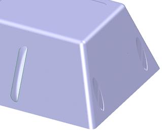
The bulge appears in the solid, but is also an independent item that can be copied, moved and mirrored.
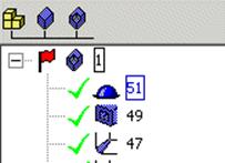
· ![]() Click the Solid Bulge on the Feature Tree.
Click the Solid Bulge on the Feature Tree.
The solid bulge becomes highlighted.
· From the Edits toolbar, select Move.
· Set copies to 1 andenter 0 30 and press return.
· Enter 0 -60 and press return.
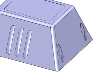
The vents have been generated for this side. They can be mirrored in turn to the other side.
· Select each bulge in turn and mirror in the YZ axis, keeping the original.
The vents bulges are mirrored. More geometry is required to make slots for the ventilation.
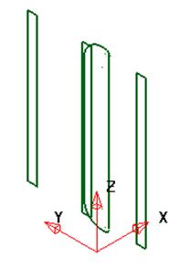
· Create a Rectangle at 0 3 15 to 0 5 82.
· Create a composite curve of this shape.
· Copy the curve by 30mm in Y either side.
The solid has been blanked to display the three new composite curves.
· Select all 3 composite curves and select solid cut
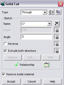
 |
· Select Through
 |
· Select both directions
· Accept
Уважаемый посетитель!
Чтобы распечатать файл, скачайте его (в формате Word).
Ссылка на скачивание - внизу страницы.