Systems Operation C27 and C32 Engines for Caterpillar Built Machines
|
Media Number --07 |
Publication Date -01/12/2008 |
Date Updated -02/12/2008 |
|
|
SMCS - 1250
|
|
|
|
View Image
|
|
|
|
|
|
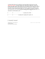
Illustration 1 |
g01087552 |
|
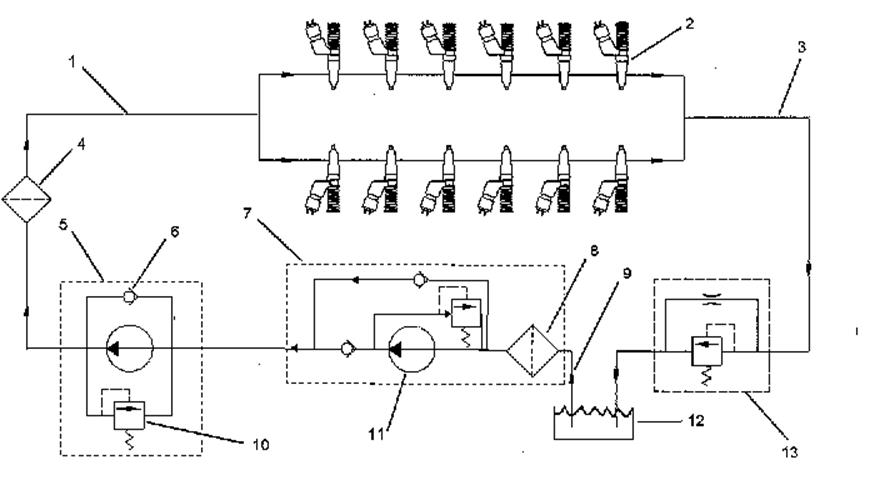
Fuel system schematic (1) Fuel gallery (2) Mechanical electronic unit injectors (3) Fuel return line (4) Secondary fuel filter (5) Fuel transfer pump (6) Check valve (7) Fuel filter base (8) Primary fuel filter (9) Fuel supply line (10) Pressure relief valve (11) Electric fuel priming pump (12) Fuel tank (13) Regulating valve |
|
The fuel supply circuit is a conventional design for unit injector diesel engines. The system consists of the following major components that are used to deliver low pressure fuel to the unit injectors:
Fuel tank - The fuel tank is used to store the fuel.
Fuel priming pump - The fuel priming pump is used to evacuate the air from the fuel system. As the air is removed the system fills with fuel.
Fuel filters - The primary fuel filter is used to remove abrasive material and contamination from the fuel system that may be large enough to damage the fuel transfer pump. The secondary fuel filter is used to remove abrasive material and contamination as small as two microns that could damage the injectors.
Supply lines and return lines - Supply lines and return lines are used to deliver the fuel to the different components.
The purpose of the low pressure fuel supply circuit is to supply fuel that has been filtered to the fuel injectors at a rate that is constant and a pressure that is constant. The fuel system is also utilized to cool components such as the fuel injectors.
Once the injectors receive the low pressure fuel, the fuel is pressurized again before the fuel is injected into the cylinder. The unit injector uses mechanical energy that is provided by the camshaft to achieve pressures that can be in excess of 200000 kPa (30000 psi).
Control of the fuel delivery is managed by the engine's Electronic Control Module (ECM). Data from several of the engine systems is collected by the ECM and processed in order to manage these aspects of fuel injection control:
The mechanical electronic fuel system relies on a large amount of data from the other engine systems. The data that is collected by the ECM will be used in order to provide optimum performance of the engine.
The flow of fuel through the system begins at fuel tank (12) . Fuel is drawn from the tank by fuel transfer pump (5) . The fuel transfer pump incorporates a check valve (6) that will allow fuel to flow around the gears of the pump during priming of the fuel system. The fuel transfer pump also incorporates a pressure relief valve (10) . The pressure relief valve is used in order to protect the fuel system from extreme pressure.
The fuel transfer pump is engineered in order to produce an excess fuel flow throughout the fuel system. The excess fuel flow is used by the system to cool the fuel system components. The excess fuel flow also purges any air from the fuel system during operation. Air that can become trapped in the fuel system can cause cavitation that may damage the components of the unit injector.
The fuel priming pump (11) is located on the fuel filter base (7) . The fuel filter base and primary fuel filter (8) also incorporates a siphon break that prevents fuel from draining from the fuel system when the engine is not in operation. The priming pump is an electric pump that directs the flow of fuel during the priming pump's operation. The filtered fuel then flows out of the fuel filter and returns to the passages in the fuel filter base. Prior to exiting the fuel filter base, the fuel pressure and the fuel temperature is sampled by the fuel pressure sensor and by the fuel temperature sensor. The signals that are generated by the sensors are used by the engine control in order to monitor the condition of the engine's components. The fuel flows through a secondary fuel filter (4) which is a two micron fuel filter. The fuel is filtered in order to remove small abrasive particles that will cause premature wear to fuel system components. This information is also used to adjust the fuel delivery
Уважаемый посетитель!
Чтобы распечатать файл, скачайте его (в формате Word).
Ссылка на скачивание - внизу страницы.