11 UART PORT
Figure 11-0.
Table 11-0. Listing 1-0.
The UART peripheral is a full-duplex, Universal Asynchronous Receiver /
Transmitter that is compatible with the industry-standard 16450. The UART converts data between serial and parallel formats. The serial communication follows an asynchronous protocol that supports various word length, stop bit, and parity generation options. This UART also contains modem control and interrupt handling hardware although only the data signals TxD and RxD are routed to pins on the ADSP-2191. Interrupts may be generated from 12 unique events.
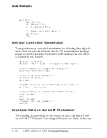
As the UART is ADSP-2191 DMA capable with support for separate TX and RX DMA Master channels, the UART may be used in either a programmed I/O mode or in a DMA mode of operation. The I/O mode requires software management of the data flow using either interrupts or polling. The DMA mode requires minimal software intervention as the DMA engine itself moves the data.
The UART and DMA Channel registers can be accessed through I/O memory space (registers). For a description of I/O memory space, see “ADSP-2191 DSP I/O Registers” on page B-1.
The UART memory map is a 16450 legacy with byte wide registers (remapped as half words with MSByte zero-filled) and the packing of multiple registers into the same address location.
The UART has two interrupt outputs referred to as the RX and TX interrupts. The TX interrupt is available in DMA mode only. In IO mode all Serial Communications
interrupts use the RX interrupt channel. Also note that in the DMA mode, the Break and Modem status interrupts are not available.
In the I/O mode, the RX interrupt is generated for all cases:
• RBR Full
• Receive Overrun Error • Receive Parity Error
• Receive Framing Error
• Break Interrupt (RXD held low)
• Modem status interrupt
• THR Empty
For information on the DMA process, see “I/O Processor” on page 6-1.
An asynchronous serial communication protocol is followed with these options:
• 5–8 data bits
• 1, 1½, or 2 stop bits
• None, even, or odd parity
• Baud rate = HCLK / (16 * DIVISOR) where DIVISOR = 1 to 65536
All data words require a start bit and at least one stop bit. This creates a range of 7 to 12 bits for each word. The format of a received and transmitted character frame is controlled by the Line Control (LCR) register. It is described Figure B-26 on page B-71. Data is always transmitted and received Least Significant Bit first.
Transmit operation is initiated by writing to the Transmit Holding (THR) register. After a synchronization delay the data is moved to the Transmit Shift (TSR) register, where it is shifted out at a baud (bit) rate equal to HCLK / (16 * DIVISOR) with start, stop, and parity bits appended as required. All data words begin with a low-going start bit. The transfer of the THR to the TSR sets the Transmit register Empty Status flag.
Figure 11-1 shows the physical bit stream as it could be measured on the TxD pin.
Data bits (5 to 8) Stop bits
Start bit LSB Parity (optional, odd or even)
Figure 11-1. Bit Stream as Measured on TxD Pin
Receive operation uses the same data format as the transmit configuration except that the number of stop bits is always one. Upon detection of the start bit, the received word is shifted in the Receive Shift (RSR) register, assuming again a bit rate of HCLK / (16 * DIVISOR). After the appropriate number of bits (including stop bits) are received, the data and status are updated, and the RSR is transferred to the Receive Buffer (RBR) register. The receive buffer register full status flag (Data Ready DR) is updated after the appropriate synchronization delay and transfer of the received word to the buffer.
A sampling clock equal to 16 times the baud rate is used to sample the data as close to the midpoint of the bit as possible. Because the internal sample clock may not exactly match the asynchronous receive data rate, I/O Mode
the sampling error (drift of sampling point from the center of each
Уважаемый посетитель!
Чтобы распечатать файл, скачайте его (в формате Word).
Ссылка на скачивание - внизу страницы.