8 HOST PORT
Figure 8-0.
Table 8-0.
Listing 8-0.
The host port interface is an 8- or 16-bit asynchronous slave to the off-chip host processor. The primary use of this interface is to provide an external host with direct access to ADSP-2191 memory space, boot space, and IO space. The ADSP-2191 acts as a slave while supporting and responding to accesses initiated by other host port masters. A host port master could be a microcontroller, FGPA, or another DSP.
This interface includes a DMA controller that eases the transfer of blocks of data between the ADSP-2191 memory/boot space and the external host processor. A functional diagram of the host port is shown in Figure 8-1.
Figure 8-1. Host Port Functional Diagram
The host port signals are listed in Table 8-1.
Table 8-1. Host Port Signals
|
Pin Name(s) |
Input/Output |
Function |
|
HAD15:0 |
I/O |
Host port multiplexed address and data bus |
|
HA16 |
I |
Host port MSB address bus |
|
HACK_P |
I |
Host ACK polarity |
|
HALE |
I |
Host port address latch strobe or address cycle control |
|
HRD |
I |
Host port read strobe |
|
HWR |
I |
Host port write strobe |
|
HACK |
I/O |
Host port access ready acknowledge |
Table 8-1. Host Port Signals (Cont’d)
|
Pin Name(s) |
Input/Output |
Function |
|
HCIOMS |
I |
Host port I/O space select |
|
HCMS |
I |
Host port memory select |
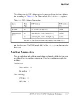
The external host or the DSP can configure host port access parameters:
• Memory/boot space map page number
• Memory/boot space data type
(internal 16-bit data access or 24-bit data access)
• Data type
• External data bus size.
The port logic provides address translation and packing/unpacking logic to allow mapping of 8-bit and 16-bit external accesses into 16-bit or 24-bit internal access data type.
The host port can function in Direct mode or host DMA mode.
• In Direct mode, the host must provide an address before initiating the data exchanges for the transaction. In Direct mode the host can access the memory space, the boot space, and the I/O space.
• In host DMA mode, the host does not have to provide an address; the address is supplied by the DMA controller embedded in the host port logic. In the host DMA mode, the host can access the memory and boot space but cannot access the I/O space.
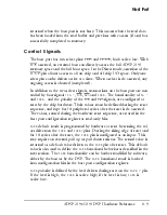
The protocol and use of control lines is configured at reset. Other parameters of the interface such as data type, byte endian-ness, or address page can be programmed by software by either the DSP core or the external host processor.
The host may use this port to directly access the entire DSP memory space map, the entire DSP boot space map, and one section of DSP I/O space map (I/O page[1:63]). Since the off-chip host has access to the complete ADSP-2191 on-chip peripheral I/O space (except page 0 space), the host may take control of any of the I/O mapped peripherals from the DSP.
Host port activity may impact DSP performance. The DSP stalls for one cycle when the host port accesses DSP internal memory. The DSP core may also have to wait in case of access conflict through the same interface. For example if both the DSP and host port try to use the external port to access external space (memory, boot, or I/O), this may result in wait periods for the DSP or the host port. Host port access to on-chip or off-chip I/O space can sometimes be accomplished without DSP cycle penalty.
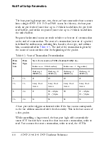
A transaction on the host port is completed when the total number of data bytes, as defined by the data type, have been transferred to the ADSP-2191 internal bus. Depending on the data bus size and the data type, as described in Table 8-2, a total of one to four host data accesses may be needed to complete the transaction.
Table 8-2. Access Cycles for One Host Transaction
|
Mode |
Data Bus Size |
Data Type |
Complete Transaction |
|
|
Host Address Cycles |
Host Data Access Cycles |
|||
|
Direct |
8 |
16 |
1 |
2 |
|
8 |
24 |
1 |
3 or (4) |
|
|
16 |
16 |
1 |
1 |
|
|
16 |
24 |
1 |
2 |
Table 8-2. Access Cycles for One Host Transaction (Cont’d)
|
Mode |
Data Bus Size |
Data Type |
Complete Transaction |
|
|
Host Address Cycles |
Host Data Access Cycles |
|||
|
Host DMA |
8 |
16 |
0 |
2 |
|
8 |
24 |
0 |
3 or (4) |
|
|
16 |
16 |
0 |
1 |
|
|
16 |
24 |
0 |
2 |
In Direct mode, an internal data transaction is composed of an address phase and a data phase, and is triggered by host access to the host port. The data can be 16-bits or 24-bits and is mapped into a packet of one, two, three, or four consecutive host accesses. Before performing a transaction, the host should have a number of parameters configured in I/O mapped registers. The parameters can be set up either by the external host or by the DSP core.
The host port memory page register should be set up to contain the most significant bits of the address that will be accessed (9 bits of memory page). The data type (16 or 24 bits) is also set up in this register. The memory space (memory or boot) that will be accessed should also
Уважаемый посетитель!
Чтобы распечатать файл, скачайте его (в формате Word).
Ссылка на скачивание - внизу страницы.