|
for EU RoHS Compliant • All the products in this catalog comply with EU RoHS. • EU RoHS is "the European Directive 2002/95/EC on the Restriction of the Use of Certain Hazardous Substances in Electrical and Electronic Equipment". • For more details, please refer to our website 'Murata's Approach for EU RoHS' (http://www.murata.com/info/rohs.html). |
|
CONTENTS |
CERAFILr and "CERAFIL" in this catalog are 1 the trademarks of Murata Manufacturing Co., Ltd.
2
2
4 3
1 5
4
2 7
3 9
5
4 11
5 13 6
6 15
7
kHz SMD Type CERAFILr Notice 17
7 19
8
8 21
MHz SMD Type CERAFILr Notice 23 9
 |
10
kHz SMD Type CERAFILr Packaging 28
30
11
9 31
33 12
35
13
37
39
14
41
43 15
45
47 16
48
17
61
Ceramic Discriminators Notice 66 18
Ceramic Discriminators Standard Land Pattern Dimensions/Packaging 69
|
o Part Numbering Ceramic Filters (CERAFILr) for IF (Part Number) SF P KA 455K D4A -R0 SF E CF 10M7 DF00 S0 -R0 q w e r t y u qProduct ID wOscillating/Element tProduct Specification
SFE/S/J series are expressed by four-digit alphanumerics. yIndividual Specification eStructure/Size SFE/S/J series are expressed by two-digit alphanumerics.
With standard type, y is omitted. uPackaging p is "A" or subsequent code, which indicates the size. It varies depending on vibration mode and number of elements. Chip type is only applied for SF series. rNominal Center Frequency Expressed by four-digit alphanumerics. The unit is hertz (Hz). If Magazine cassette is applied to lead type and embossed taping to the unit is "kHz", it is expressed by three figures plus "K". If the chip type. unit is "MHz", a decimal point is expressed by the capital letter "M". |
|
Ceramic Discriminators for IF (kHz) (Part Number) CD B LB 450K C A X 16 -B0 q w e r t y u i o qProduct ID
eStructure/Size
p is "A" or subsequent code, which indicates the size. It varies depending on vibration mode and number of elements. rNominal Center Frequency Expressed by four-digit alphanumerics. The unit is in hertz (Hz). Capital letter "K" following three figures expresses the unit of "kHz". tDetection
yApplication
|
uElement Type
iIC
oPackaging
Magazine cassette is applied to lead type and embossed taping to chip type. With non-standard products, one letter indicating "Individual Specification" is added between "iApplicable IC" and "oPackage Specification code". |
||||||||||||||||||||||||||||||||||||||||||||||
|
Ceramic Discriminators for IF (MHz) (Part Number) CD S CB 10M7 GF 001 -R0 q w e r t y u qProduct ID
p is expressed "A" or subsequent code, which indicates the size. rNominal Center Frequency Expressed by four-digit alphanumerics. The unit is in hertz (MHz). Decimal point is expressed by capital letter "M". |
tProduct Specification
yIC
With non-standard products, an alphanumerics indicating "Individual Specification" is added between "yIC" and "uPackaging". |
Products Guide
oSMD Type (kHz)
oLead Type (kHz)
1
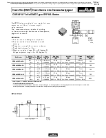
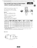
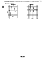
The SFPKA series is comprised of small, high performance, economical, thin (5.0mm) filters consisting of 4 ceramic elements.
Their innovative construction is perfect for shrinking mobile communication products such as cordless phones, pagers and transceivers.
■ Features
1. The filters are mountable by automatic placers.
2.  The filters can be reflow soldered and withstand (in mm) washing.
3. They are slim, at only 5.0mm maximum thickness.
4. The bandwidth ranges from D to H.
5. Operating temperature range: -20 to +80 (degrees C) Storage temperature range: -40 to +85 (degrees C)
|
Part Number |
Center Frequency (fo) (kHz) |
6dB Bandwidth (kHz) |
Stop Bandwidth (kHz) |
Stop Band Attenuation (dB) |
Insertion Loss (dB) |
Ripple (dB) |
Input/Output Impedance (ohm) |
|
SFPKA455KD4A-R1 |
455 ±1.5kHz |
fn±10.0 min. |
fn±20.0 max. [within 40dB] |
27 min. [within fn±100kHz] |
4.0 max. [at minimum loss point] |
2.0 max. [within fn±7kHz] |
1500 |
|
SFPKA455KE4A-R1 |
455 ±1.5kHz |
fn±7.5 min. |
fn±15.0 max. [within 40dB] |
27 min. [within fn±100kHz] |
6.0 max. [at minimum loss point] |
1.5 max. [within fn±5kHz] |
1500 |
|
SFPKA455KF4A-R1 |
455 ±1.5kHz |
fn±6.0 min. |
fn±12.5 max. [within 40dB] |
27 min. [within fn±100kHz] |
6.0 max. [at minimum loss point] |
1.5 max. [within fn±4kHz] |
1500 |
|
SFPKA455KG1A-R1 |
455 ±1.0kHz |
fn±4.5 min. |
fn±10.0 max. [within 40dB] |
25 min. [within fn±100kHz] |
6.0 max. [at minimum loss point] |
1.5 max. [within fn±3kHz] |
1500 |
|
SFPKA455KH1A-R1 |
455 ±1.0kHz |
fn±3.0 min. |
fn±9.0 max. [within 40dB] |
35 min. [within fn±100kHz] |
6.0 max. [at minimum loss point] |
1.5 max. [within fn±2kHz] |
2000 |
Center frequency (fo) defined by the center of 6dB bandwidth.
(fn) means nominal center frequency 455kHz.
For safety purposes, connect the output of filters to the IF amplifier through a D.C. blocking capacitor. Avoid applying a direct current to the output of ceramic filters.
The order quantity shoud be an integral multiple of the "Minimum
Уважаемый посетитель!
Чтобы распечатать файл, скачайте его (в формате Word).
Ссылка на скачивание - внизу страницы.