|
Mounting instructions |
TO126; SOT82 |
1. Fasten the device to the heatsink before soldering theleads.
2. Avoid stress to the leads.
3. Keep mounting tool (e.g. screwdriver) clear of theplastic body.
CLIP MOUNTING (TO126 AND SOT82) Mounting with a spring clip gives:
a) A good thermal contact under the crystal area, andslightlylowerthermalresistancethanscrewmounting.
b) Safe insulation for mains operation.
Minimum force for good heat transfer is 10 N.
Maximum force to avoid damaging the device is 80 N.
M2.5 AND M3 SCREW MOUNTING (TO126 ONLY)
It is recommended that a metal washer is inserted between the screw head and the device.
Do not use self-tapping screws.
Mounting torque for screw mounting:
Minimum torque for good heat transfer is 0.40 Nm.
Maximum torque to avoid damaging the device is
0.60 Nm.
Whenthedriven nutisindirectcontactwithatoothedlock washer the torques are as follows:
Minimum torque for good heat transfer is 0.55 Nm.
Maximum torque to avoid damaging the device is
0.80 Nm.
BODY MOUNTING (SOT82)
The SOT82 envelope can be adhesive mounted or soldered onto a hybrid circuit.
For soldering, a copper plate or an anodised aluminium plate with a copper layer is recommended.
The device may be adhesive mounted directly onto a ceramic substrate.
Minimum thickness: 2 mm.
Flatness in the mounting area: 0.02 mm maximum per 10 mm.
Mounting holes must be deburred, for further information see clip and screw mounting instructions.
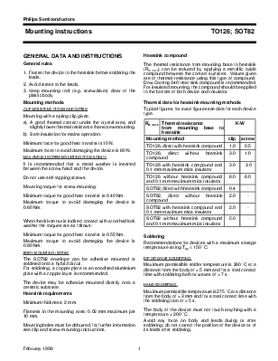
The thermal resistance from mounting base to heatsink
(Rth mb-h) can be reduced by applying a metallic oxide compound between the contact surfaces. Values given are of thermal resistance using this type of compound. Dow Corning 340 Heat sink compound is recommended. For insulated mounting, the compound should be applied to the bottom of both device and insulator.
Typical figures, for exact figures see data for each device type.
|
Rth mb-h |
Thermal resistance from mounting base to heatsink |
K/W |
|
|
Mounting method |
clip |
screw |
|
|
TO126,direct withheatsinkcompound |
1.0 |
0.5 |
|
|
TO126, direct without heatsink compound |
3.0 |
1.0 |
|
|
TO126 with heatsink compound and 0.1 mm maximum mica insulator |
3.0 |
3.0 |
|
|
TO126 without heatsink compound and 0.1 mm maximum mica insulator |
6.0 |
6.0 |
|
|
SOT82,directwithheatsinkcompound |
0.4 |
- |
|
|
SOT82, direct without heatsink compound |
2.0 |
- |
|
|
SOT82 with heatsink compound and 0.1 mm maximum mica insulator |
2.0 |
- |
|
|
SOT82 without heatsink compound and 0.1 mm maximum mica insulator |
5.0 |
- |
|
Recommendations for devices with a maximum storage temperature rating Tstg ≤ 150 ˚C:
DIP OR WAVE SOLDERING.
Maximum permissible solder temperature is 260 ˚C at a distance from the body of > 5 mm and for a total contact time with soldering bath or waves of < 7 s.
HAND SOLDERING.
Maximumpermissibletemperatureis275 ˚Catadistance from the body
Уважаемый посетитель!
Чтобы распечатать файл, скачайте его (в формате Word).
Ссылка на скачивание - внизу страницы.