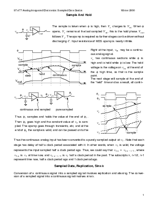
remains at the last sampled Vin, this is the hold phase. Vout
follows Vc. The opamp is required so further stages can be driven without discharging C. Input resistance of MOS opamp is nearly infinite.
 Right at
the input, vin
may be a continuous analog signal.
Right at
the input, vin
may be a continuous analog signal.
vc has continuous sections while φ is high and is held while φ is low. The held voltage is the voltage on vin at the end of the φ high time, so that is the sample point.
The next stage will sample at the end of the “held” time and as a result, all contin-
continuous and sampled pure sampled
Thus φ1 samples and holds the value at the end of φ1.
Then φ2 goes high and the constant value of vo is sampled. The opamp goes through transients, etc, and at the end of φ2 the sample is valid, and can be passed on to the
Thus the continuous analog input has been converted to a purely sampled output at v2. Note that each stage has delay of half a clock period associated with it. In other words, when v2 is valid, the voltage represents the input sampled half a clock period ago. Thus, we could say that v2 n = vi n –1 ⁄ 2, where v2 n is v2 at time now, and vi n –1 ⁄ 2 is vi half a clock period in the past. The subscripts n, n-1/2, n-1 represent time now, half a clock period ago and 1 clock period ago.
Conversion of a continuous signal into a sampled signal involves replication and aliasing. The conversion of a sampled signal into a continuous signal involves sinx/x.
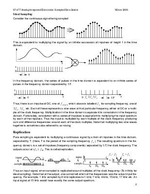
This is equivalent to multiplying the signal by an infinite succession of impulses of height 1 in the time domain.
In the frequency domain, the series of pulses in the time domain is equivalent to an infinite series of pulses in the frequency domain separated by 1/T.

Thus, there is an impulse at DC, one at f clock which above is labelled f s for sampling frequency, one at
2 f s , 3 f s etc. Each of these represents a sine wave at that particular frequency, either at DC or a multiple of the clock frequency. Multiplication in the time domain is equivalent to convolution in the frequency domain. Fortunately, convolution with a series of impulses is equivalent to multiplying the input spectrum by each of the impulses. Thus the input is multiplied by each multiple of the clock frequency producing sum and difference frequencies around each of the clock multiples. Note that multiplying two sine waves together is sometimes also referred to as mixing.
Pure sampling is equivalent to multiplying a continuous signal by a train of impulses in the time domain, separated by T. (Here, T is the period of the sampling frequency f s .) The resulting spectrum in the frequency domain, is a set of impulses (frequency components) separated by 1/T, the clock frequency. The outputs occur atn f s ± f in. This is called replication.
 f
s – f i f + f
f
s – f i f + f
inputinput
XXf
samplesample
fs 2fs 3fs
Thus an input signal, when sampled is replicated around multiples of the clock frequency (To infinity for ideal sampling). Note that at the output, one cannot tell which of the frequencies was the actual input frequency. For example, 1 kHz sampled by 8 kHz replicates to 1 kHz, 7 kHz, 9 kHz, 15 kHz, 17 kHz etc. An input signal at 15 kHz would have exactly the same output spectrum.
 If a S.C. filter is
built at baseband, frequencies input close to n f s
will
If a S.C. filter is
built at baseband, frequencies input close to n f s
will
Уважаемый посетитель!
Чтобы распечатать файл, скачайте его (в формате Word).
Ссылка на скачивание - внизу страницы.