VARIABLE LENGTH OF DATA FRAMES: Included in the identifier field are two bits indicating the length of the message field (see Table 1). This adds flexibility and reduces overhead bytes when only a limited amount of data is required.
MULTI-CAST RECEPTION: When a message frame is transmitted from the master or a slave task, all connected nodes in the network can read the message. Depending on the identifier byte, the receiving nodes decides if any action is to be initiated or not. For example, a single “CLOSE ALL” command from the master could be accepted from all nodes and could in the case of a car security system close all windows and doors.
TIME SYNCHRONIZATION WITHOUT NEED FOR QUARTZ OR CERAMIC RESONATORS IN THE SLAVE
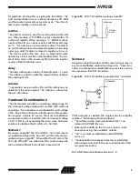
NODES: After the Synch Break, a Synch Field is transmitted from the master, this field makes it possible for all the slaves to synchronize to the master clock. Such synch fields are placed at the beginning of every message frame. The accuracy of the receiving slaves need only be good enough to keep synchronization through the entire message frame. This feature allows the slave to run on an internal RC oscillator thus reducing the overall system cost.
DATA CHECKSUM SECURITY AND ERROR DETEC-
TION: The data in the message frame uses an inverted modulo256-checksum with the carry of the MSB added to the LSB for error detection. In addition, the identifier byte uses a XOR algorithm for error detection.
DETECTION OF DEFECT NODES IN THE NETWORK:
The master task is responsible for initiating the transmission of message frames and thus has the responsibility of requesting information and checking that all nodes are alive and working correctly.
MINIMUM COST SOLUTION: Due to the simplicity of the protocol, a slave task complying to the LIN standard can be built using a minimum of external components and does not put heavy constraints on the accuracy of the oscillator in the slave nodes.
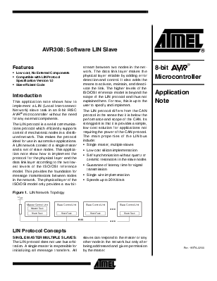
The LIN bus consists of a single channel that carries both data and synchronization information. The physical medium is a single wire connected to VCC via a pull-up resistor (see Figure 1). The idle state on the bus is high or “recessive” and the active state is low or “dominant”. In automotive applications VCC will typically be the positive battery node.
The LIN protocol does not define an acknowledgment procedure for the slave tasks. The master task uses its own slave task to verify that the sent message frame is identical with the one received by this slave task. If any discrepancy is detected the message frame can be retransmitted.
The data rate for transmitted data is limited to 20 Kbits/s due to EMI (Electro Magnetic Interference) requirements for a single wire transmission medium.
All information transmitted on the LIN bus is formatted as Message Frames. As shown in Figure 2, a Message Frame consists of the following fields:
• Synch Break
• Synch Field
• Identifier Field
• Data Field
• Checksum Field
Figure 2. LIN Message Frame
The message frame consists of two parts: the “header” sent
Уважаемый посетитель!
Чтобы распечатать файл, скачайте его (в формате Word).
Ссылка на скачивание - внизу страницы.