HEAVY-DUTY TRANSPORT VEHICLE TRANSMISSION ELECTROHYDRAULIC DEVICES CONTROL
Andrey A. Mahanko
Automatics and Control Department
Kazan State Technical University named after A.N.Tupolev
Karl Marx str. 10, Kazan, 420111, RUSSIA
e-mail: andmahanko@mail.ru
Abstract – variants of control of heavy-duty transport vehicle mechanical transmission by electrohydraulic devices are considered.
1. Introduction
Hydraulic devices and systems are widely used for heavy transport. It is conditioned by the high energy intensity of hydraulic systems, by its ability of the energy transferring, although not for a long distance (hydrostatic transmissions, hydraulic drives of attached equipment and handling devices) and also by the ability of the hydraulic systems flexible control. Traditionally, distributors and valves with manually operated mechanical drives are used for hydraulic systems control. Nowadays, we need to use electrohydraulic distributors and valves to get a possibility to integrate the hydraulic systems of a transport vehicle to united control system, that requires solving of many tasks, concerned with its application.
2. TRANSPORT VEHICLES ELECTROHYDRAULIC SYSTEMS
Hydraulic systems are used for heavy-duty vehicles in the follow three cases:
- hydrostatic transmissions,
- attached equipment hydraulic drives,
- hydraulic devices of mechanical transmission.
Hydrostatic transmissions are used in cases, when we need to provide flexible control of the vehicle or vehicle left and right sides opposite operate possibility. Hydrostatic transmission consists of set of hydraulic pump – hydraulic motor pairs for each driven vehicle device (left and right side of tractor). Electrovalves, guiding of pumps and motors gain, are used in case of electrical control (axial-plunger pumps and motors swash plate bevel angle).
Attached equipment hydraulic drives usually are high pressure hydraulic cylinders, that move attached equipment (mold blade, ripper, handling device, reaper and so on). Flow rate control hydraulic valves, that adjust hydraulic fluid feed or bleed-off from hydraulic cylinder, are used for control of such systems. In case of electrical control the system is created so way, that electrical signal defines flow rate control valve position.
Different types of hydraulic devices are used for mechanical transmissions. For instance, it could be torque converters, that provide according of engine operate and vehicle moving. Hydraulic devices of transmission control are also widely used.
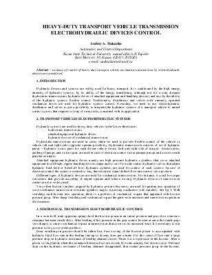
Very often friction clutches, gripped by hydraulic pistons (boosters), are used for putting into operation of some mechanical transmission elements (gearbox stages, traversing mechanism side clutches). See fig.1. With switching such booster into operation, there is a problem of mechanical impact that appeared with booster pressure jump. After sharp switching and mechanical impact the parts wear increases and transmission operation life decreases.
3. MECHANICAL TRANSMISSION ELECTROHYDRAULIC CONTROL
In a switch off state opposing springs hold the booster piston in an initial position and provide a minimum clearance between clutch disks. After feeding of full pressure in the gear control booster at once, the clutch grips very sharply so causes mechanical impact in transmission that comes to its increased wear. It is nesessary to rise pressure slowly to solve this problem.
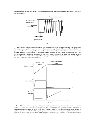
Gear switching-on process should be rather fast. Fast moving of the booster piston is accompanied with hydraulic fluid flow rate in the feeding line up to dozens liters per minute. For this value of flow rate a large pressure drop on hydraulic resistance of feeding channels arises. There is a low pressure in the booster. After a piston moving finish, when the clearance between discs are closed, flow rate actually fall down to zero. Pressure drop on the hydraulic resistance of feeding channels disappeared, that creates pressure jump in the booster, causing hard clutch switching-on and impact in the transmission. Thus, gear switching-on process is divided to two phases (fig.2).
 |
Уважаемый посетитель!
Чтобы распечатать файл, скачайте его (в формате Word).
Ссылка на скачивание - внизу страницы.