One of this problem solving ways is the gear switching-on is made by discrete valve, but there is some system of modulator valves works accordingly to it, that do not let pressure booster to arise too fast. Pressure changing evenness in these valves is provided by hydraulic liquid by-pass from booster to drain through a system of jets and control valves. During this system operation we do not manage to completely avoid pressure peak in the end of filling booster phase and filling parameters are strongly depended of oil characteristics (for instance, after temperature decreasing on 60° modulator operation time – pressure increasing – arises twice). System of this type do not require electronic control system, and it used by Caterpillar company in 80th.
The other way of this problem solving is to set a proportional electrohydrovalve of pressure control in the booster inlet and to form its control signal to avoid a pressure jump.
Comatsu company patented industrial tractor gear box clutch booster pressure control system with electrohydrovalves [2]. In this system different types of booster pressure pickups for pressure feedback signal forming are used. However, sluggishness of modern electromagnets brings too much delay into the system operation, that do not allow to change the system pressure enough quickly to compesate pressure jump during filling. It is nessary to have quick-acting electromagnets or to compesate the delay by correcting units for effective system operation.
After beginning of introduction of modern microprocessors into a heavy-duty transport vehicles transmission control systems we get a possibility of open-loop program control systems creation, when the electrovalve gets signal depending on time only U=f(t), but for which forming the changing of parameters, affecting on the system behavior, is taken into account.
We should can correct the control law U=f(t) in the real-time mode after changing of factors values, that affect the system behavior (such as temperature, supply voltage and so on). The mostly effective way of such system development is research with the help of mathematical model. The fully functional realization of such system is possible on the base of microprocessor system with high-current input devices (amplifiers, semiconductor switches).

Fig.3
The control signal form that required for gear booster switching-on, is shown on the fig.3. In the beginning the push is given, that opens the control valve and allows quickly fill the booster cylinder. At the end of the filling phase the signal decreases down to level, allowing finishing the filling without the transmission impact. After the booster closing the pressure arise takes place, it is firstly slow, providing gearing acceleration without jerks and shocks, and then it is fast, allowing finish the gear positioning during the less time.
(a)

(b)
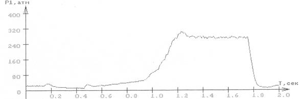
Fig. 4
The mathematical modeling results of booster putting into operation and further switching off process (booster moving, control signal, booster pressure) are given on a fig. 4(a), the fig. 4 (b) shows real booster test record (pressure). In this case control law parameters are chosen not optimally and pressure jump takes place, that lead to mechanical impact in the gear box.
(а)
(b)
Fig. 5
In the fig. 5 the results of modeling (a) and experimental research (b) of the same booster and controller valve, but with using of optimal control parameters, are shown. Avoidance of pressure jump in this case eliminates impact in the transmission and prolongs its operation life.
4. CONCLUSION
Different ways of the heavy-duty transport vehicle gear-box boosters switching-on electrohydraulic system control were considered. The most optimal variant from all considered is usage of modulating valve for booster pressure control and microprocessor system for the control signal forming, which form depends on transmission position.
5. LITERATURE
1. Bashta T.M. Hydrodrive and Hydropneumoautomatics. Moscow, Mashinostroenie, 1972.
2. Berezovskij A.B., Chefanov V.M. Hydraulic system analysis: tutorial. KSTU named after A.N.Tupolev. Kazan, Kazan State Technical University Press, 2000.
3. Device For Hydraulic Pressure Control In The Hydraulic Cylinder Friction Clutch Drive. Patent SU 1753958 A3. Class F 16 D25/14, F 15 B 11/10, F 16 H 43/00.
Уважаемый посетитель!
Чтобы распечатать файл, скачайте его (в формате Word).
Ссылка на скачивание - внизу страницы.