![]() Caution:
Caution:
n When cabinets are arranged side by side, their alarms can be concatenated with alarm concatenation cables and then output together to the centralized alarm system, as shown in Figure 7-16.
n The concatenation cable between any two subracks in a cabinet has been installed before delivery, while that between two adjacent cabinets can be installed in the same way as other alarm input/output cables led out of the cabinet.
|
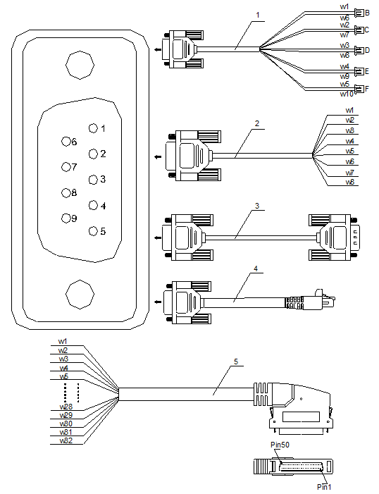
1. Cabinet alarm indicator cable |
2. Alarm output cable |
3. Alarm concatenation cable (for the OptiX OSN 9500) |
|
3. Alarm concatenation cable (for the OptiX OSN1500/2500/3500) |
3. Alarm input cable |
Figure 7-13 Outer view of external alarm cables
Table 7-3 Pin assignment of cabinet indicator driving cable
|
Pin |
Connector on the cabinet |
Wire |
Remarks |
|
1 |
B1 |
W1 |
Power ground |
|
2 |
C1 |
W2 |
Red indicator output |
|
3 |
D1 |
W3 |
Yellow indicator output |
|
4 |
E1 |
W4 |
Orange indicator output |
|
5 |
F1 |
W5 |
White indicator output |
|
6 |
B2 |
W6 |
+5 V |
|
7 |
C2 |
W7 |
+5 V |
|
8 |
D2 |
W8 |
+5 V |
|
9 |
E2/F2 |
W9/W10 |
+5 V |
Table 7-4 Pin assignment of alarm concatenation cable
|
Pin |
Core color |
Remarks |
|
1 |
Black |
GND |
|
6 |
Black/white |
Major alarm |
|
3 |
Red |
GND |
|
7 |
Red/white |
Critical alarm |
|
4 |
Brown |
GND |
|
8 |
Brown/white |
Minor alarm 1 |
|
5 |
Orange |
GND |
|
9 |
Orange/white |
Minor alarm 2 |
Table 7-5 Pin assignment of alarm concatenation cable
|
Core |
Pin of cable connector |
Core |
Pin of cable connector |
|
W1 |
1 |
W17 |
9 |
|
W2 |
14 |
W18 |
22 |
|
W3 |
2 |
W19 |
10 |
|
W4 |
15 |
W20 |
23 |
|
W5 |
3 |
W21 |
11 |
|
W6 |
16 |
W22 |
24 |
|
W7 |
4 |
W23 |
12 |
|
W8 |
17 |
W24 |
25 |
|
W9 |
5 |
W25 |
26 |
|
W10 |
18 |
W26 |
39 |
|
W11 |
6 |
W27 |
27 |
|
W12 |
19 |
W28 |
40 |
|
W13 |
7 |
W29 |
28 |
|
W14 |
20 |
W30 |
41 |
|
W15 |
8 |
W31 |
29 |
|
W16 |
21 |
W32 |
42 |
Table 7-6 Pin assignment of alarm output cable
|
Core |
Meaning |
|
W1 |
Critical alarm |
|
W2 |
Major alarm |
|
W3 |
Minor alarm 1 |
|
W4 |
Minor alarm 2 |
|
W5 |
Critical alarm GND |
|
W6 |
Major alarm GND |
|
W7 |
GND of minor alarm 1 |
|
W8 |
GND of minor alarm 2 |
Уважаемый посетитель!
Чтобы распечатать файл, скачайте его (в формате Word).
Ссылка на скачивание - внизу страницы.