Consider now transient
response of the servomechanism to a ramp input (Fig.1.4b). In the early stages
of the input (instant ![]() ), and while the error
signal is small, the load accelerates slowly and lags behind the input. The
signal increases as the lag increases, thereby building up the acceleration.
Eventually the input and loud speeds are equal (instant
), and while the error
signal is small, the load accelerates slowly and lags behind the input. The
signal increases as the lag increases, thereby building up the acceleration.
Eventually the input and loud speeds are equal (instant ![]() ),
but since a substantial position error exists, the load continuous to
accelerate. Then the acceleration is reduced, and the load attains a constant
speed (instant
),
but since a substantial position error exists, the load continuous to
accelerate. Then the acceleration is reduced, and the load attains a constant
speed (instant ![]() ) at zero position error
with no error signal, and so on. Thus, as in the case of a step input, a
continuous oscillation is produced.
) at zero position error
with no error signal, and so on. Thus, as in the case of a step input, a
continuous oscillation is produced.
If there are coloumb and viscous frictions the oscillations are damping (Fig.1.4). But using only inherent friction light damping is achieved. It is necessary, therefore, to use special approaches to restrict the oscillations.
The actuator is intended for activity in a structure of the servomechanism as an actuator of the autopilot and mechanically connected to a control system of an airplane.
The main characteristics:
Voltage
across the winding of excitation of the engine ![]()
Voltage
across the winding of control of the engine ![]()
The
firing moment of the engine ![]()
Voltage
across the winding of excitation of a tachogenerator ![]()
Steepness
of voltage output of a tachogenerator not less ![]()
Steepness
of voltage output of the induction potentiometer not less ![]()
Power
of engine DG – 25B ![]()
Efficiency
of the reduction gearbox ![]()
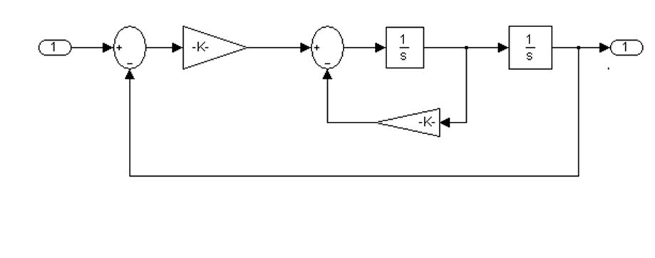
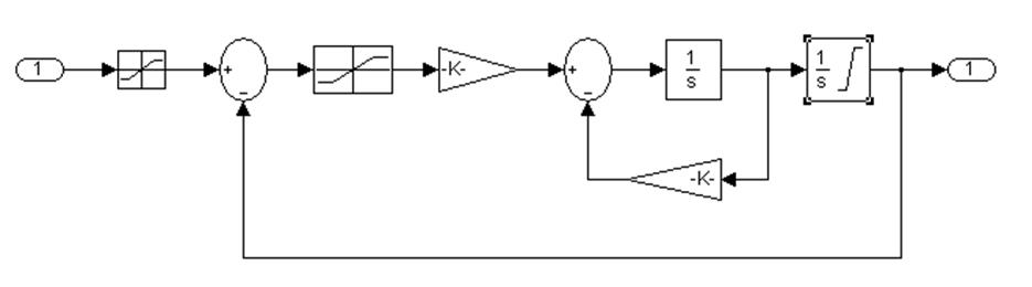
The given block diagrams of linear and non-linear servomechanisms we find in mathematical packet MATLAB 6.1 as follows:
1. We start MATLAB;
2. In a command line we write Demos;
3. In menu MATLAB Demos Simulink it is chosen Aerospace in which menu it is chosen Electrohydraulic Servomechanisms;
4. We receive schemes of linear and non-linear servomechanisms;
|
|
|
|
 Nonlinearservomechanism
|
|
|
|
|
|
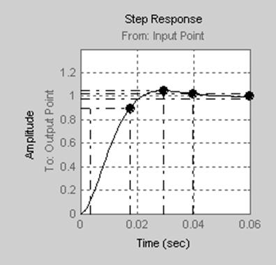
Drawing of transient characteristics (of linear servomechanism) is made under following scheme
|
|

Linear Nonlinear
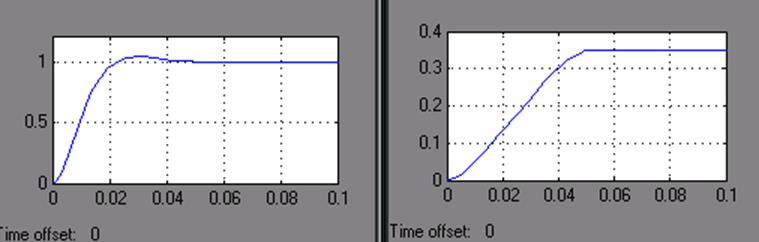
From the received schedules it is visible, that the system is steady.
Settling time ![]()
Overshoot ![]()
Research of frequency response of servomechanisms
Research of frequency response we shall conduct on linear model.
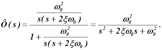
To draw frequency characteristics it is necessary to receive a transfer function of a servomechanism.
Transfer function of closed-loop system is
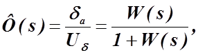
where ![]() -
transfer function of disconnected system
-
transfer function of disconnected system
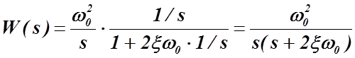
proceeding from this

The logarithmic amplitude frequent characteristic,
The logarithmic phase frequent characteristic,
The amplitude-phase frequent characteristic,
Drawing LAFC, LPFC , MPFC with the help of commands Bode, Nyquist.
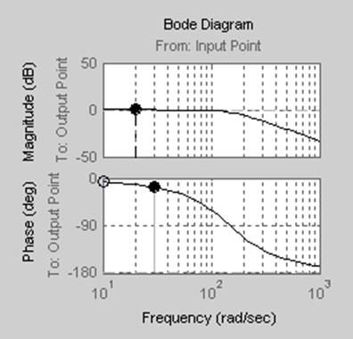
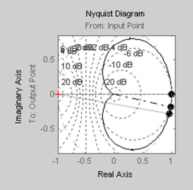
From the received schedules it is visible, that the system is absolutely steady.
The principal diagram of the final cascade of the servomechanism amplifier

Fig. 2.1. The final cascade of the amplifier
It is
necessary to choose transistors ![]() for obtaining in load of voltage
for obtaining in load of voltage ![]() and a current
and a current ![]() .
.
We choose the
amplifier of general application ![]() . Its basic parameters:
. Its basic parameters:
![]()
![]()
![]()
3. Maximum voltage on a collector
![]()
Taking into account values
![]() , we choose transistors
, we choose transistors ![]() и
и ![]() . Their basic parameters:
. Their basic parameters:![]()
These transistors meet the
requirements on permissible ![]()
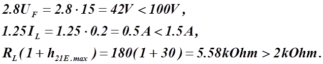
![]()
![]() , transistors
, transistors ![]() can be used without heat
rejections.
can be used without heat
rejections.
5. ![]()
6. Power supply voltage
of the amplifier ![]()
7. ![]()
![]()
![]()
At ![]() transistors
transistors ![]() are open for currents:
are open for currents:
![]() , that is the amplifier
provides a current of load
, that is the amplifier
provides a current of load
![]() .
.
10. Maximum voltage ![]() of transistors
of transistors![]() :
:
![]() .
.
11. Power, which
dissipates on transistors![]() :
:
![]() .
.
Taking into account the received values, we choose
transistors ![]()
12. Currents of bases of transistors![]() :
:
![]() .
.
13. Currents of dividers ![]() and
and ![]() also should exceed
considerably
also should exceed
considerably![]() . We receive
. We receive ![]() .
.
Whence ![]()
14.
Resistance
of resistors ![]() it is considered, taking into
account
it is considered, taking into
account ![]() :
:
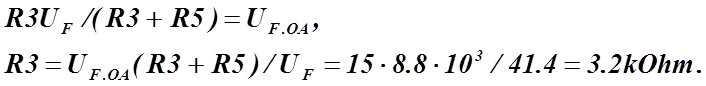
Means, ![]()
We receive ![]()
15. Capacitor
![]()
The analysis standard TP and selection of operations
Analyzing standard TP, we choose operations for worker TP [11].
table
Уважаемый посетитель!
Чтобы распечатать файл, скачайте его (в формате Word).
Ссылка на скачивание - внизу страницы.