![]()
![]() Notes and Discussions
Notes and Discussions![]()
no harm is done •by ma-king the demonstration easily visible to hundreds of students.
The authors gratefully acknowledge several useful suggestions from Marius Isaila.
![]() E. M. Purcell, Electricity and
Magnetism, VOL 2, Berkeley Physics Course (McGraw-Hill, New York, 1965).
Section 7.12 and particularly Fig. 7.31 on p. '262 deals specifically with this
point.
E. M. Purcell, Electricity and
Magnetism, VOL 2, Berkeley Physics Course (McGraw-Hill, New York, 1965).
Section 7.12 and particularly Fig. 7.31 on p. '262 deals specifically with this
point.
Simple Laser Test for Uniform Carriage
Motion in Interferometers
L. JOHN GAGLIAIU)I
![]() Ph.ysics
Dcparbncnt
Ph.ysics
Dcparbncnt
Rutgers Universit.y
Camden, Neu Jersey 08102
(R.eeeived 12 July 1973; revised 28 August 1973)
A simple procedure to check for uniformity of advance of the movable element of an interferometer is described in this note. Using this procedure, a record of the uniformity of motion over the entire travel is obtained from which the positions of possible, trouble spots may be easily
![]()
determined.
![]()
It is most important that the motion
of the ![]() carriage.
on which the movable, element of an interferometer is mounted follow the
micrometer
carriage.
on which the movable, element of an interferometer is mounted follow the
micrometer ![]() advance
continuously. Often, the carriageways
advance
continuously. Often, the carriageways
![]()
are not completely smooth and/or the carriage
![]()
![]()
![]()
![]()
![]()
![]()
![]()
![]()
![]()
![]()
![]()
![]()
![]()
![]()
![]()
![]()
![]()
![]()
![]()
![]()
![]()
![]()
![]()
![]()
![]() gliders become worn. These conditions, separately
gliders become worn. These conditions, separately
![]()
![]() or in cornbination, result in an imperceptibly jerky
advance of the movable element, with the carriage ' 'hanging up"
frequently as it travels. This condition may exist only along a very small
portion of the track in an otherwise precise and
or in cornbination, result in an imperceptibly jerky
advance of the movable element, with the carriage ' 'hanging up"
frequently as it travels. This condition may exist only along a very small
portion of the track in an otherwise precise and
![]()
![]() well-maintained instrument. The results of even
well-maintained instrument. The results of even ![]() a
very limited segment being in this condition can be quite serious in terms of
the. resulting experimental errors. As a practical matter, it is wise to
consider an interferometer suspect until
a
very limited segment being in this condition can be quite serious in terms of
the. resulting experimental errors. As a practical matter, it is wise to
consider an interferometer suspect until ![]() proven
otherwise.
proven
otherwise.![]()
The following procedure may be used to
check the entire travel for uniform carriage. motion with micrometer advance.
To make the discussion spe-![]()
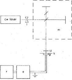
![]() FIG. 1.
Schematic diagram of experirnental arrangement for test of uniform motion of
the movable element, in a Michelson interferometer.
FIG. 1.
Schematic diagram of experirnental arrangement for test of uniform motion of
the movable element, in a Michelson interferometer.
cific, the procedure will be explained for a Michelson
interferometer. The basic arrangement is ![]() shown
in Fig. 1; similar arrangements can be
shown
in Fig. 1; similar arrangements can be![]()
![]()
used for several other
types of interferonwters. A ![]()
![]()
![]() low power, cw laser is directed through a diverging lens
and into the Michelson interferometer m. The fringes arc projected onto an
inexpensive photodiode p mounted behind a screen s and
low power, cw laser is directed through a diverging lens
and into the Michelson interferometer m. The fringes arc projected onto an
inexpensive photodiode p mounted behind a screen s and
variable slit st. The screen, which is used for visual alignment of the fringes, permits exposure of the detector through a fixed slit with a width
![]() approximately equal to the maximum aperture of the
variable slit. The detector system consists of a Keithley 610C electrometer e
and a strip-chart recorder r. The recorder drive is attached through a gear box
(not shown) to the carriage advance, of the interferometer. In this fashion, a
plot of the variation in intensity as the fringes sweep
approximately equal to the maximum aperture of the
variable slit. The detector system consists of a Keithley 610C electrometer e
and a strip-chart recorder r. The recorder drive is attached through a gear box
(not shown) to the carriage advance, of the interferometer. In this fashion, a
plot of the variation in intensity as the fringes sweep
AJP Vol.u,mc 42 / 249
Уважаемый посетитель!
Чтобы распечатать файл, скачайте его (в формате Word).
Ссылка на скачивание - внизу страницы.