![]() Our apparatus is based on a large capacitor with two
80-cm-diam aluminum plates, held apart with a 10-cm spacing. The lower plate is
grounded, and the upper plate, has a banana plug in the top so that, the
connection to it may easily be opened and closed. The capacitor is driven from
a small powdered iron torus transformer (Ferroxcube 400 T 750) which is wound
with a ratio of 50 primary to 1000 secondary turns. This matches the capacitor
to a 600 Q audio oscillator
Our apparatus is based on a large capacitor with two
80-cm-diam aluminum plates, held apart with a 10-cm spacing. The lower plate is
grounded, and the upper plate, has a banana plug in the top so that, the
connection to it may easily be opened and closed. The capacitor is driven from
a small powdered iron torus transformer (Ferroxcube 400 T 750) which is wound
with a ratio of 50 primary to 1000 secondary turns. This matches the capacitor
to a 600 Q audio oscillator
Nolcs and Discussions
(Hewlett Packard, Model 200CD or equivalent,) , so that there is a voltage of one hundred volts
![]()
across the capacitor at about '20 kHz.![]()
![]() The magnetic induction pickup coil is in thc form of a
torus and is made as follows: A 238-cmlong, 1.27-cm-radius rubber vacuum hose
is wound
The magnetic induction pickup coil is in thc form of a
torus and is made as follows: A 238-cmlong, 1.27-cm-radius rubber vacuum hose
is wound ![]() with
14 000 turns of No. 38-gauge Formvar insu-
with
14 000 turns of No. 38-gauge Formvar insu- ![]() lated
wire. This can be donc by threading a dowel through the tubing and using a hand
drill as a
lated
wire. This can be donc by threading a dowel through the tubing and using a hand
drill as a ![]() rotating
device. The wire is glued onto the tube with silicone RTV cement just to
fogilitate han
rotating
device. The wire is glued onto the tube with silicone RTV cement just to
fogilitate han![]()
![]() dling.
The wire is insulated and protected against
dling.
The wire is insulated and protected against
![]()
abrasion by a larger thin rubber hose, (1.27-cm inside, radius, 4-mm thick wall) which is slit lengthwise, slipped over the coil and taped securely with mylar tape.
![]() Copper
shielding foil is added as shown in Fig.
Copper
shielding foil is added as shown in Fig. ![]() 2(b)
; the tubing is bent into a circle, excess end
2(b)
; the tubing is bent into a circle, excess end ![]()
![]()
rubber is cut off, and the tubing plus shielding is ![]()
![]()
![]() attached
to a piece of plywood backing in order
attached
to a piece of plywood backing in order ![]() to
hold it rigidly. The plywood piece hos a large
to
hold it rigidly. The plywood piece hos a large![]()
![]()
hole cut in the middle. and has a handle as shown![]()
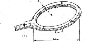
![]() in Fig. 2(a). At the junction of the handle. and
in Fig. 2(a). At the junction of the handle. and ![]() the
torus, the two ends of the toroidal coil are brought to a 1:1 audio-output
transformer with
the
torus, the two ends of the toroidal coil are brought to a 1:1 audio-output
transformer with![]()
![]()
secondary center tapped.
(b) 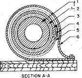
![]()
![]()
![]() FIG. 2. (a)
Toroidal coil assembled on plywood or phenolic bourd brace. (b) Cross section
A—A of toroidal coil showing: (l) rubber tubing form; (2) wire windings; (3)
outer insulating tubing; (4) Mylar tope to insulate overlapping portion of (5)
cepper shielding foil • about 0.0025 cm thick; (6) plastic hose or coble clamp.
FIG. 2. (a)
Toroidal coil assembled on plywood or phenolic bourd brace. (b) Cross section
A—A of toroidal coil showing: (l) rubber tubing form; (2) wire windings; (3)
outer insulating tubing; (4) Mylar tope to insulate overlapping portion of (5)
cepper shielding foil • about 0.0025 cm thick; (6) plastic hose or coble clamp.
AJP Volume 42
/ 247![]()
Notes and Discussions
Probably any audio interstage transistor
transformer will do here, but ours was made from a powdered iron Ferroxcube
528T 500 toroidal form wound with 400 turn primary and 400 turn center-tapped
secondary. In order to be, conservative about stray pickup, the secondary was
wound with 20() turns right-handed, and 200 turns overwound left-handed, and
the starting points of these two coils were used as the common secondary center
tap which was connected to the shielding foil. The secondary of this
transformer is led by two shielded RG/59U or equivalent cables to the
differential input amplifier terminals of a ![]() laboratory
type oscilloscope.
laboratory
type oscilloscope.
![]() It is important to notice that this type of connection,
from the coil to the oscilloscope, is essential to the elimination of unwanted
stray
It is important to notice that this type of connection,
from the coil to the oscilloscope, is essential to the elimination of unwanted
stray ![]() pickup
Voltages. The desired signal is push-pull or differential in na.ture. The small
1 :1 trans
pickup
Voltages. The desired signal is push-pull or differential in na.ture. The small
1 :1 trans![]() former
helps to reject the common-mode pickup voltage. Common-mode, rejection is
improved by
former
helps to reject the common-mode pickup voltage. Common-mode, rejection is
improved by ![]() using
an oscilloscope (in our case a Tektronics
using
an oscilloscope (in our case a Tektronics ![]() 503)
with a good differential amplifier input with sensitivity of about 1 mV/cm. Thc
shielding of the coil is important, and it also helps greatly to incltlde the
small transformer mentioned within the copper foil shielding. The center tap of
the transformer secondary is grounded to the shielding.
503)
with a good differential amplifier input with sensitivity of about 1 mV/cm. Thc
shielding of the coil is important, and it also helps greatly to incltlde the
small transformer mentioned within the copper foil shielding. The center tap of
the transformer secondary is grounded to the shielding.
Уважаемый посетитель!
Чтобы распечатать файл, скачайте его (в формате Word).
Ссылка на скачивание - внизу страницы.