Notes and Discussions
which are controlled by a single, spring-return (center-off)
SP3T toggle switch mounted in a hand-held unit on a cable. ![]()
I would like to acknowledge, the
substantial ![]() contributions
of R. N. Euwema and J. A. Elmgren in developing this experiment.
contributions
of R. N. Euwema and J. A. Elmgren in developing this experiment.
1 See, for instance, J. W. M. DuMond and E. R. Cohen, Rev. Mod. Phys. 25, 691 (1953).
![]() 2 A. C. Melissinos, Experiments in Modern Physics
(Academic, New York, 1966), pp. 2—8; The Taylor Manual, edited by T. B. Brown
(Addison—Wesley, Reading, MA, 1959), pp. 392-94.
2 A. C. Melissinos, Experiments in Modern Physics
(Academic, New York, 1966), pp. 2—8; The Taylor Manual, edited by T. B. Brown
(Addison—Wesley, Reading, MA, 1959), pp. 392-94. ![]()
![]() H. Kruglak, Am. J Phys. 40, 768
(1972).
H. Kruglak, Am. J Phys. 40, 768
(1972). ![]()
![]() 6 The posting of the original A At
values in addition to the computed A V—1 M-3 /2 gives the instructor
a chance to spot gross arithmetic blunders, which occur all too frequently.
6 The posting of the original A At
values in addition to the computed A V—1 M-3 /2 gives the instructor
a chance to spot gross arithmetic blunders, which occur all too frequently.
6 E. Whittaker and G. Robinson, The Calculus of
Observations (Von Nostrand, Princeton, NJ, 1944), 4th ed. sec. 101, 104.![]()
![]() 7 Similar to Experiment EF-I, A. M.
Portis and H. D. Young, Berkeley Physics Labora.toriol (McGraw—Hill, New York,
1971), 2nd ed.
7 Similar to Experiment EF-I, A. M.
Portis and H. D. Young, Berkeley Physics Labora.toriol (McGraw—Hill, New York,
1971), 2nd ed. ![]()
![]()
Direct "Literal" Demonstration of the
![]()
![]() Effect of a Displacement Current
Effect of a Displacement Current
![]() THOMAS R. CARVER
THOMAS R. CARVER
JAN RAJHEL
Joseph Henry Laboratories
Departnunt of Physics ![]()
Princeton University
Princeton, New Jersey 08540
(Received 26 June 1973; revised 17 July 1973)
![]()
![]()
![]() Maxwell's displacement current density is one of the
physical concepts—like magnetic induction in Faraday's Law—that requires the
freshmen
Maxwell's displacement current density is one of the
physical concepts—like magnetic induction in Faraday's Law—that requires the
freshmen ![]() physics
students to understand changing flux and
physics
students to understand changing flux and ![]() circuital
line integral paths. These concepts seem
circuital
line integral paths. These concepts seem ![]() to
be anomalously diffcult to understand. Although the existence of
electromagnetic radiation might seem to be an adequate test of Maxwell's
to
be anomalously diffcult to understand. Although the existence of
electromagnetic radiation might seem to be an adequate test of Maxwell's ![]() theory
and a demonstration of displacement currents, one often feels a more literal
demonstration of displacement current is needed. This note, de-
theory
and a demonstration of displacement currents, one often feels a more literal
demonstration of displacement current is needed. This note, de- ![]() scribes
a lecture-demonstration apparatus which shows the effect of the displacement
current between two capacitor plates and introduces the student to the
motivating idea that an induced circuital magnetic field is produced not only
by a real current in a wire leading to a capacitor plate, but also—in the sense
of continuity—by
scribes
a lecture-demonstration apparatus which shows the effect of the displacement
current between two capacitor plates and introduces the student to the
motivating idea that an induced circuital magnetic field is produced not only
by a real current in a wire leading to a capacitor plate, but also—in the sense
of continuity—by ![]() the
displacement current between capacitor plates.
the
displacement current between capacitor plates.
Our apparatus is simple: A toroidal coil is either
placed around a wire leading to a large pair of capacitor plates to demonstrate Ampere's law, or the toroidal coil is inserted between the capacitor plates as shown in mg. 1 to demonstrate
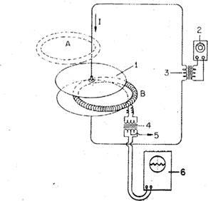
FIG. 1. Schematic of general setup of the demonstration showing toroidal coil in position A for Ampere's law and in position B for displacement currents: (1) capacitor plates; (2) audio oscillator; (3) matching or driving transformer described in text; (4) output transformer described in text; (5) center tap of output transformer grounded to coil shield
|
246 / March 1974 |
(not shown) and to cable shielding leading to oscilloscope; (6) differential input, fairly high gain, low frequency oscilloscope.
the effect of the displacement current. A magnetic field produced by the alternating currents of either form in the right hand terms of
B.dl=go ( 1+0ffddEt •dS)
![]()
induces, by Faraday's law,
![]()
an alternating voltage which is displayed on an
oscilloscope and also on a large lecture slave, oscilliscope. The concept is
completely obvious to most physicists, but the, reader who substitutes a.ct,ual
numbers into the above equations for a suitably sized capacitor and coil and
for convenient choices of ac frequencies will find that the induced voltage is
inconveniently small. Moreover, if one must contend with a small voltage
signal, then the stray capa.citive. pickup voltagc will mask the desired
effect. For example, if one, uses a 10 000-turn ![]() toroidal
coil of about a 30—40 cm diam, with a cross-sectional area of about 10 cm2,
and uses large capacitor plates with a spacing of 6—10 cm that are driven at 60
Hz by a small neon-sign transformer at several kilovolts, then the induced
voltage is little more than a few microvolts and
toroidal
coil of about a 30—40 cm diam, with a cross-sectional area of about 10 cm2,
and uses large capacitor plates with a spacing of 6—10 cm that are driven at 60
Hz by a small neon-sign transformer at several kilovolts, then the induced
voltage is little more than a few microvolts and ![]() the
unwanted pickup signal will be more than a few volts. Alternately, if one
chooses a frequency which is high, such as 1 MHz, then special equipment such
as a radio-frequency amplifier and a fast scope will be required. We believe
that the demonstrati(jn set-up described in this note comes
the
unwanted pickup signal will be more than a few volts. Alternately, if one
chooses a frequency which is high, such as 1 MHz, then special equipment such
as a radio-frequency amplifier and a fast scope will be required. We believe
that the demonstrati(jn set-up described in this note comes
![]()
close to optimal simplicity and, except for the construction of the coil itself, requires no special apparatus that is not commonly available in a physics laboratory or lecture-demonstration stockroom.
Уважаемый посетитель!
Чтобы распечатать файл, скачайте его (в формате Word).
Ссылка на скачивание - внизу страницы.