When critical alarm occurs in the equipment, the critical alarm terminal will be connected to the critical alarm ground so as to output critical alarm signal. When major alarm occurs in the equipment, the major alarm terminal will be connected to the major alarm ground so as to output major alarm signal. The short-circuit is achieved by using a relay. The principle is shown in Figure 1-7. If there is an alarm, a corresponding relay will close and provide the alarm ground to centralized alarm system.
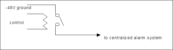
Figure 1-7 Schematic diagram of alarm external connection
On PDA board, because the corresponding pins of J9 and J10 are short circuited one by one, the manner of output is similar.
If multiple racks are placed in rows, cascade alarm mode can be adopted. The alarm signal can be cascaded from one rack to another, and the last rack sends the signal to the column head rack. Inter-rack connection is shown in Figure 1-8.

Figure 1-8 Alarm external cascaded connection mode
n J11 is the external alarm input connector
PDA board provides six input connectors for external alarms. This alarm access function is designed mainly for remote monitoring on the alarm parameters of external systems (such as environment monitoring system). The user can configure the six paths of alarms to be what kind of alarm, so that the system can perform external alarm remote monitoring function jointly with the external systems.
![]() Note:
Note:
The transmission system is not able to fulfill independently the monitoring function through inputting alarm signals from the external equipment. It should cooperate with external equipment of the user.
Circuit principle diagram of J11 is shown in Figure 1-9.
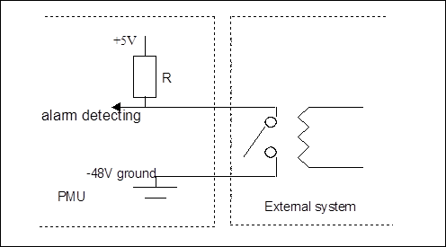
Figure 1-9 Circuit principle diagram of J11 pin
From this figure it is obvious that the external alarm can be accessed by setting whether the external alarm signal is effective at low electrical level or at high electrical level. (If the external alarm is accessed via a relay, it should be set whether the alarm is effective when the relay are closed or open.) Pin relation of J11 is shown in Figure 1-10.
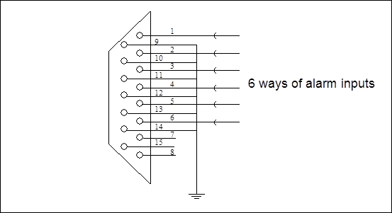
Figure 1-10 Connection schematic diagram of J11 pin
2. PMU board
The main functions of PMU (Power Monitor Unit) are as follows:
1) Generate the ringing current.
2) Monitor the voltage:
Two paths of -48V power input voltage can be monitored. There are four alarm points of voltage monitoring: serious under-voltage (-36V), common under-voltage (-41V), common over-voltage (-60V), and serious over-voltage (-72V).
3) Detect the temperature
Temperature detection is performed by the temperature sensor placed in the power box. It should be noted here that the detected result is the ambient temperature in the rack, not the temperature of the subrack or board.
4) Monitor the alarms
6 ways of external input alarms and 2 ways of equipment alarms (critical alarm and major alarm of upper/lower subrack) are monitored, and it features corresponding equipment alarm output and external environment monitoring functions.
The toggle switches on the PMU are shown in Figure 1-11.

Figure 1-11 Schematic diagram of the toggle switch
Respective positions of the toggle switch are as follows:
1 —reserved.
2 —Selection of PMU to communicate with the upper or lower subrack. When it is set to the upper position, PMU communicates with the upper subrack; when it is set to the lower position, PMU communicates with the lower subrack. PMU can not communicate with the two subracks simultaneously.
Уважаемый посетитель!
Чтобы распечатать файл, скачайте его (в формате Word).
Ссылка на скачивание - внизу страницы.