|
1.1 Rack Structure
1.1.1 Structure Diagram
OptiX BWS 320G backbone DWDM optical transmission system (hereinafter called “OptiX BWS 320G system”) rack is composed of a main skeleton, a door in the front and a back door fixed by screws at the back. Left and right sides are mounted with side panels. Inside the rack, the power box is installed at the very top, right under the power box is a top ODF subrack. The equipment subrack is installed in the middle and lower part of the rack; one rack can accommodate two equipment subracks at most. The fan subrack is installed right under each equipment subrack. The disassembly diagram of the overall structure of OptiX BWS 320G rack is shown in Figure 1-1.
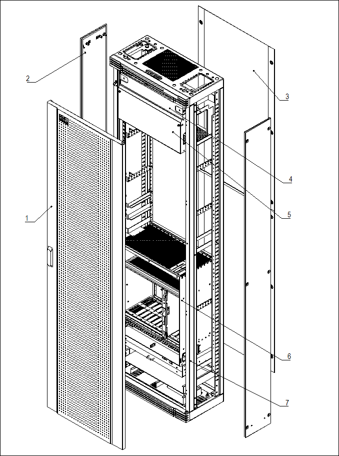
Note: 1.Front door; 2. Side panel; 3. Back door; 4. Power box; 5. ODF subrack; 6.Subrack; 7. Skeleton.
Figure 1-1 Disassembly diagram of OptiX BWS 320G rack
1.1.2 Physical Parameters
ETSI standard rack is used in OptiX BWS 320G DWDM optical transmission equipment. There are three kinds of racks available, with dimensions and weights as follows:
n 2000mm(height)×600mm(width)×300mm(depth), 64kg;
n 2200mm(height)×600mm(width)×300mm(depth), 70.4kg;
n 2600mm(height)×600mm(width)×300mm(depth), 80kg.
1.2 Power Box
1.2.1 Instruction of Power Box
OptiX BWS 320G employs standard -48V DC power supply. The -48V DC power, output from the power supply device, is transmitted to the working subrack through the power box, which will also monitor the alarms of power supply and environment. There are two power sockets (Power1 and Power2) at the interface area of the working subrack. The two power sockets can be connected with -48V DC power respectively. In normal working condition, the protective ground should be grounded soundly. When the power plug is pulled out or put in, the power should be off. Figure 1-2 illustrates the front view of the power box at the top of the rack.
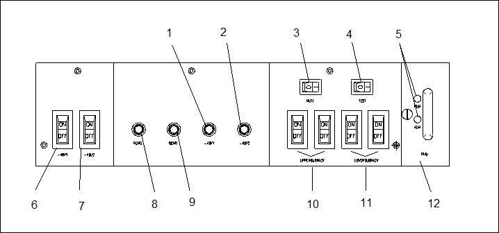
Note: 1. –48V (the first general switch); 2. –48V (the second general switch); 3. Alarm clearing switch; 4. Sound/light test switch; 5. Indicator; 6. Master switch (the first line); 7. Master switch (the second line); 8. Protection ground; 9. Powerground; 10. Power switch of the upper subrack; 11. Power switch of the lower subrack; 12. PMU board.
Figure 1-2 Front view of the power box
In the following part every item in the above figure will be elaborated.
On the panel of the power box, there are four power distribution pole, "PGND", "BGND"," -48V1", "-48V2". When making cable connection, make sure that the blue cable is connected to the "-48V1" or the "-48V2"; the black one to the "BGND", and the yellow-green cable to the "PGND". After the rack is supplied with power, the potential difference between the blue cable and the black cable, is to be measured with a multi-meter so as to ensure it is in the permitted range (-38.4V ~ -57.6V). The "BGND" and "PGND" are combined outside the rack through the outside grounding cable, the cable between "BGND" and "PGND" is not permitted to be removed.
On the panel of the power box, there are four power switches for the subracks. Among them, two "UPPERSUBRACK" switches (being backup of each other) supply power to the upper subrack in the rack, while two "LOWERSUBRACK" switches (being backup of each other) to the lower subrack. When the "UPPERSUBRACK" or the "LOWERSUBRACK" switchs are switched on, the upper or the lower subrack are supplied with -48V power.
On the panel of the power box, there are two control alarm switches for the subracks. The "MUTE", is the alarm mute switch. The alarm can be shut off when the "MUTE" is turned on. The "TEST", is the alarm test switch. When the switch is switched on, the green, red and yellow indicators of the rack top will flash simultaneously, and the buzzer will sound, indicating that the alarm system is normal.
On the panel of the power box, there are two general power switches for the subracks. By the "-48V1"and "-48V2" general power switch, two external -48V DC power can be switched on or switched off individually. When two external power are not independent, "-48V1" and "-48V2" are connected by wire, and that is regarded as two -48V DC power. When the equipment is powered on, the "-48V1"and "-48V2" general power switch must be switched on. When the equipment is powered off, the "-48V1"and "-48V2" general power switch must be switched off.
Уважаемый посетитель!
Чтобы распечатать файл, скачайте его (в формате Word).
Ссылка на скачивание - внизу страницы.