n OPU board: 1
When lightning happens, OPU board can make fast response to the transient high voltage generated on the -48V power supply lines and restrict the power supply voltage of the rack within an acceptable range, thus ensuring the safe operation of the equipment.
Moreover, there are two fuse tubes F1 and F2 on the OPU. F1 protects the upper subrack, while F2 the lower subrack. If any abnormality causes F1 or F2 to break, new fuse tubes with the same rating current can be used to replace them.
The following will focus on the functions, applications of the power distribution adapter (PDA) board, and the power monitoring unit (PMU) in the power box.
1. PDA board
PDA(Power Distribution Adapter Unit), is also called rack power distribution adapter board.
There are 6 D-shaped pins(J6~J11)on PDA board, their functions are as follows:
n J6~J7 connectors
These two connectors are communication sockets for power box and the subrack, normally J6 corresponding to the upper subrack and J7 corresponding to the lower subrack. The connector pins at both ends of the subrack connection wire are shown in Figure 1-5.
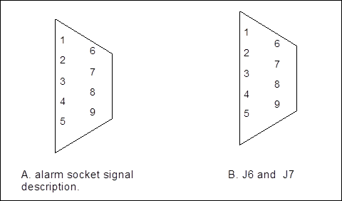
Figure 1-5 Schematic diagram of the power socket and J6 and J7 pins
The interface of subrack alarm and the J6(J7) is one to one corresponding, interface description:
1. CALL: orderwire ringing current(AC 75V)can reach more than 100V;
2. YALM1/2 : upper(lower) subrack yellow indicator alarm(low voltage available);
3. RALM1/2: upper(lower) subrack red indicator alarm(low voltage available);
4. ALMGND: alarm ground;
5. ALM1: control buzzer(bell when low voltage);
6. CALL: orderwire ringing current(AC 75V)can reach more than 100V;
7. T1/2: serial port transmitting end, communicate with upper(lower)subrack;
8. R1/2: serial port receiving end, communicate with upper(lower)subrack;
9. ALMGND: alarm ground.
J8 interface is the reserving interface, not available.
n J9 and J10 pin
The two interfaces are alarm output interfaces of the equipment. First, the alarm signal from upper (lower) subrack is received by PDA board through J6 (J7) interface. Then, the signal is delivered to PMU board through PDA board. Finally, the signal is sent to PDA board after being processed by PMU board and is delivered to centralized alarm system.
OptiX BWS 320G equipment has two types of alarms: visible alarm, including red alarm indicator (for critical alarm) and yellow alarm indicator (for major alarm), and audio alarm which is signaled by a buzzer. At present, the audio alarm is mainly triggered by critical alarm. When the SCC board delivers critical alarm to power box, the red indicator is on with the buzzer sounding. The sound can be muted or resumed by the alarm mute switch (MUTE) at the top of the rack or the alarm cancel switch (ALC) on the SCC board. The OptiX BWS 320G equipment supports the applications to connect the alarm signal of the rack to centralized alarm system.
The power box provides two ways of alarm interfaces for OptiX BWS 320G equipment. One is the interface for critical alarm and the other is the interface for major alarm. When the alarm signal of equipment is output through J9 or J10 on the PDA, the connection is as shown in Figure 1-6.
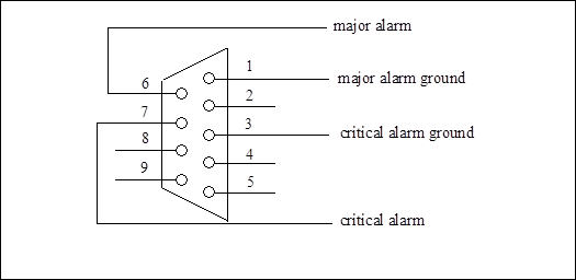
Figure 1-6 J9 and J10 pin diagram
Уважаемый посетитель!
Чтобы распечатать файл, скачайте его (в формате Word).
Ссылка на скачивание - внизу страницы.