Contents
2 Network Topology 2-1
2.1 Common Network Topology 2-1
2.2 Chain Network 2-3
2.2.1 Application 2-3
2.2.2 Protection Mode 2-3
2.3 Ring Network 2-9
2.3.1 Application 2-9
2.3.2 Protection Mode 2-9
2.4 Ring with Chain Network 2-17
2.4.1 Application 2-17
2.4.2 Protection Mode 2-17
2.5 Other Topologies 2-24
Figures
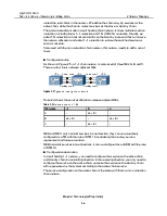
Figure 2-1 Chain with chain network 2-3
Figure 2-2 Board configuration of NE A and NE C 2-4
Figure 2-3 Board configuration of NE D 2-5
Figure 2-4 Board configuration of NE B 2-5
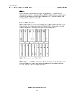
Figure 2-5 Typical self-healing chain network 2-6
Figure 2-6 Board configuration of NE A and NE C 2-7
Figure 2-7 Board configuration of NE B 2-8
Figure 2-8 Typical ring network 2-10
Figure 2-9 Service flow between NE A and NE C (normal) 2-11
Figure 2-10 Service flow between NE A and NE C (fiber-cut) 2-11
Figure 2-11 Board configuration of NE A 2-12
Figure 2-12 Service flow between NE A and NE C (normal) 2-13
Figure 2-13 Service flow between NE A and NE C upon fiber cut (ring switching) 2-14
Figure 2-14 Service flow between NE A and NE C upon fiber cut (span switching) 2-15
Figure 2-15 Typical configuration of NE A 2-16
Figure 2-16 MSP ring with chain network 2-17
Figure 2-17 Active service flow between NE A and NE E 2-18
Figure 2-18 Switching of service from NE A to NE C 2-19
Figure 2-19 Board configuration of NE D 2-20
Figure 2-20 Typical ring with chain network 2-20
Figure 2-21 Active service flow between ring and chain (A¨E) 2-21
Figure 2-22 Protection switching of service between ring and chain 2-22
Figure 2-23 Board configuration of NE A 2-23
Figure 2-24 Board configuration of NE D 2-23
Tables
Table 2-1 Network topology 2-2
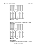
Table 2-2 Service allocation of NEs 2-3
Table 2-3 Service allocation of NEs 2-6
Table 2-4 Comparison of the two protection modes 2-9
Table 2-5 Service allocation of NEs 2-10
Table 2-6 Service allocation among nodes 2-18
Table 2-7 Service flow between NE A and NE E and the configuration of NE D 2-19
Table 2-8 Service between nodes 2-20
Table 2-9 Service flow between NE A and NE E and the configuration of NE D 2-22
This chapter introduces the possible network topologies constructed by the OptiX OSN 3500, as well as the features, application and protection modes of some common networks. It includes:
n Common network topology
n Chain network
n Ring network
n Ring with chain network
n Other topologies
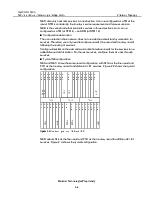
The OptiX OSN 3500 can realize the chain or ring networking at any level of STM-1, STM-4, STM-16, or STM-64, and some complex networks, such as tangent rings, intersecting rings, ring with chain, dual node interconnection (DNI), and HUB network (combination of ring and chain networks), as shown in Table 2-1.
The topology type and protection mode of an optical transmission network should be determined by the practical line structure, service type, traffic and protection requirements, to protect services through the networking plan and data settings. The ring network is preferred.
Уважаемый посетитель!
Чтобы распечатать файл, скачайте его (в формате Word).
Ссылка на скачивание - внизу страницы.