Chain network and ring network are the two basic topologies. Topologies derived from them like ring with chain, intersecting rings, and tangent rings are often adopted by an optical transmission network. This chapter focuses on the application, features, and protection modes of these network topologies.
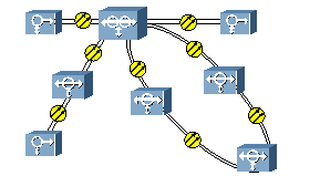
Table 2-1 Network topology
|
No. |
Topology type |
Topology |
|
1 |
Chain network |
|
|
2 |
Ring network |
|
|
3 |
Tangent rings |
|
|
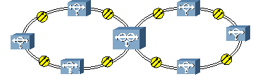
4 |
Intersecting rings |
|
|
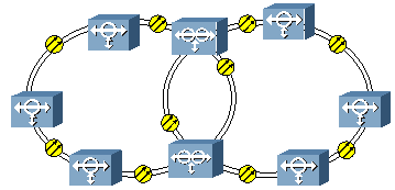
5 |
Ring with chain |
|
|
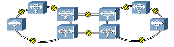
6 |
Dual node interconnection (DNI) |
|
|
7 |
HUB network |
|
|
Legend: |
||
As a basic network topology, the chain network is adopted when services centralize between adjacent NEs or when the ring network is not applicable (for example, a network is along the railway).
Some topologies such as chain with chain network are derived from the chain network.
The service on chain may adopt unprotected mode, or 1+1, 1:1 or 1:N self-healing protection. Select the protection mode according to the practical requirements, such as the importance of service and the utilization of bandwidth (whether adding additional services).
It is quite simple to configure a chain without protection. Here takes a chain with chain network as an example to introduce the configuration of non-protection chain.
n Configuration plan
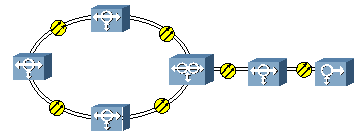
Figure 2-1 is a chain with chain network. All the services are unprotected.

Figure 2-1 Chain with chain network
In Figure 2-1, NE A, NE B, and NE C are on the main chain, NE B and NE D are on the side chain, the two chains meet at NE B. There are E1 services between NEs, with the service allocation listed in Table 2-2.
Table 2-2 Service allocation of NEs
|
Node |
A |
B |
C |
D |
|
A |
- |
63 x E1 |
- |
- |
|
B |
63 x E1 |
- |
63 x E1 |
32 x E1 |
|
C |
- |
63 x E1 |
- |
- |
|
D |
- |
32 x E1 |
- |
- |
NE A and NE C only transmit services in one direction. They can be respectively configured as a TM at the rate of STM-16 considering the tributary service requirement and future expansion.
NE D also only transmits services in one direction. It can be configured as a TM at the rate of STM-4 considering the tributary service requirement and future expansion.
NE B is the central node that transmits services in three directions, so it can be configured as a TM (at STM-4) + an ADM (at STM-16).
n Configuration description
The non-protection chain network does not provide the active/standby protection for services. Therefore, you only need to configure boards (line board and tributary board) following the routing of services.
Configure timeslots on the east and west optical interface boards for the services to be added/dropped at this station. For the rest services, configure them as pass-through services.
n Typical NE configuration
NE A and NE C share the same board configuration, with SL16 as the line board and PQ1 as the tributary board to add/drop 63 x E1 services. Figure 2-2 shows the typical configuration.
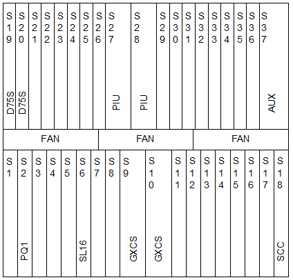
Figure 2-2 Board configuration of NE A and NE C
NE D adopts SL4 as the line board and PQ1 as the tributary board to add/drop 32 x E1 services. Figure 2-3 shows the typical configuration.
Уважаемый посетитель!
Чтобы распечатать файл, скачайте его (в формате Word).
Ссылка на скачивание - внизу страницы.