Contents
5 Fan Tray Assembly 5-1
5.1 Structure 5-1
5.2 Principle 5-3
5.3 Front Panel 5-4
5.4 Specifications 5-5
Figures
Figure 5-1 Location of the fan tray assembly and air filter in the subrack 5-2
Figure 5-2 The OptiX OSN 9500 fan tray assembly 5-3
Figure 5-3 Functional block diagram of the JFAN 5-3
Figure 5-4 Front panel of the fan tray assembly 5-4
This chapter introduces the structure, principle, front panel and specifications of the fan tray assembly.
5.1 Structure
The OptiX OSN 9500 employs two fan tray assemblies for subrack heat dissipation. These two fan tray assemblies are respectively seated in the front and rear frames of the subrack, using the backplane for power supply. Supporting hot swapping, they are very convenient in maintenance. Moreover, these two fan tray assemblies are placed with an air filter separately in the subrack, as shown in Figure 5-1.
|
1. Fan tray assembly |
2. Air filter |
3. Subrack |
Figure 5-1 Location of the fan tray assembly and air filter in the subrack
The fan tray assembly is composed of three fans and a fan control board (JFAN). Figure 5-2 shows its architecture. As the air filter is positioned under the subrack (separated from the fan tray assemblies), it can be taken out directly for cleaning purpose.

|
1. Handle |
2. Antistatic hole |
3. Alarm label |
4. Name plate |
|
5. Fan indicator |
6. Captive screw |
7. Fan |
Figure 5-2 The OptiX OSN 9500 fan tray assembly
5.2 Principle
Induced draft is adopted as the heat dissipation mode for the OptiX OSN 9500. Independently designed, the two fan tray assemblies are housed in the upper part of the subrack frames, getting power supply from the system backplane directly.
The fan control board is abbreviated to JFAN hereinafter.
Figure 5-3 Functional block diagram of the JFAN
The functional modules of the JFAN are shown in Figure 5-3, including power processing module, speed regulation module and monitoring & indication module. The JFAN connects with the EMPU and JPIU via the connectors connecting the backplane. The numerals in the above diagram stand for the corresponding number of the signal line.
n Power processing module: filters and protects the direct current (DC) power supply, and performs voltage stabilization and voltage linear reduction to the –48 V power supply to feed the respective unit circuits of the JFAN with the 5 V power supply finally got.
n Speed regulation module: receives the speed control signal from the EMPU and regulates the rotational speeds of the fans.
n Monitoring & indication module: monitors the rotational speed of each fan, and displays the collected fan statuses by the indicators on the front panel of the fan tray assembly, thus making the alarms visible. The interface signals being processed include the fan status signal from the EPMU and the status signals generated by the monitoring unit of the JFAN.
5.3 Front Panel
Figure 5-4 shows the front view of the front panel of the fan tray assembly.
Figure 5-4 Front panel of the fan tray assembly
Description of the indicators on the front panel of the fan tray assembly is shown in Table 5-1.
Table 5-1 Description of the front panel indicators of the fan tray assembly
|
No. |
Indicator name |
Description |
|
1 |
Green running indicator (RUN) |
There are totally three of them, indicating normal operation of the three fans respectively. On: fan operates normally. Off: fan operates abnormally (abnormal rotational speed or fan not-in-position). |
|
2 |
Red alarm indicator (ALARM) |
Indicates whether the fan tray assembly is in normal operation. On: fan or the JFAN is abnormal. Off: fan or the JFAN is normal, or power disconnection occurs in the fan tray assembly. |
Relationship between the fan indicators and status of the fan tray assembly is shown in Table 5-2.
Table 5-2 Relationship between the fan indicators and the fan status
|
Fan tray assembly status |
Green indicator |
Red indicator |
|
Normal |
On |
Off |
|
Equipment not powered on |
Off |
Off |
|
One of the fans is not-in-position, stops rotating or fails |
Off |
On |
|
EMPU failure |
On |
On |
& Note:
If the EMPU goes wrong, the JFAN board fails to receive the speed control signal. In such case the fans will rotate at their highest speeds.
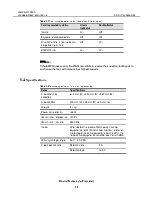
5.4 Specifications
Table 5-3 Technical specification for the fan tray assembly
|
Items |
Specifications |
|
|
Size of fan tray assembly |
61.5 mm (H) x 243 mm (D) x 487 mm (W) |
|
|
Size of JFAN |
300 mm (H) x 35 mm (D) x 2.0 mm (w) |
|
|
Weight |
4.1 kg |
|
|
Power consumption |
128 W |
|
|
Maximum wind pressure |
140 Pa |
|
|
Maximum air volume |
250 CFM |
|
|
Noise |
When tested in a place 600mm away from the equipment and of 1500mm over the floor, and when the temperature of the equipment room is 25°C, the noise of the equipment should be less than 60 dBA. |
|
|
Working voltage range |
46 V – 50 V DC |
|
|
Fuse specifications |
Rated current |
4 A |
|
Rated voltage |
125 V |
|
Уважаемый посетитель!
Чтобы распечатать файл, скачайте его (в формате Word).
Ссылка на скачивание - внизу страницы.