Contents
7 Installing Cables 7-1
7.1 Installing Power Cables and Grounding Cables 7-3
7.1.1 Procedures in Upward Cabling Mode 7-4
7.1.2 Procedures in Downward Cabling Mode 7-8
7.1.3 Installation Check 7-10
7.2 Installing STM-1 Cables 7-11
7.2.1 Procedures in Upward Cabling Mode 7-12
7.2.2 Procedures in Downward Cabling Mode 7-14
7.2.3 Installation Check 7-15
7.3 Installing Alarm Cables 7-16
7.3.1 Procedures in Upward Cabling Mode 7-17
7.3.2 Procedures in Downward Cabling Mode 7-23
7.3.3 Installation Check 7-24
7.4 Installing Clock Cables 7-26
7.4.1 Procedures in Upward Cabling Mode 7-27
7.4.2 Procedures in Downward Cabling Mode 7-29
7.4.3 Installation Check 7-30
7.5 Installing NM Cables 7-31
7.5.1 Procedures in Upward Cabling Mode 7-32
7.5.2 Procedures in Downward Cabling Mode 7-33
7.5.3 Installation Check 7-35
7.6 Installation Check Points 7-35
Figures
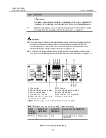
Figure 7-1 Connection positions for the power cable and the grounding cable 7-5
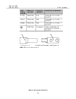
Figure 7-2 Outer view of power connectors 7-6
Figure 7-3 Connect the grounding lug 7-7
Figure 7-4 Wire the power cable and the grounding cable in upward cabling mode 7-7
Figure 7-5 Bind the power cable label 7-8
Figure 7-6 Extend the power cable and the grounding cable 7-8
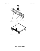
Figure 7-7 Wire the power cable and the grounding cable in downward cabling mode 7-10
Figure 7-8 SMB coaxial connector 7-11
Figure 7-9 Outer view of JLHE 7-12
Figure 7-10 Wire the STM-1 cable in upward cabling mode 7-13
Figure 7-11 Affix a label 7-14
Figure 7-12 Wire the STM-1 cable in downward cabling mode 7-15
Figure 7-13 Outer view of external alarm cables 7-18
Figure 7-14 Positions of alarm interfaces 7-21
Figure 7-15 Wire the external alarm cables in upward cabling mode 7-22
Figure 7-16 Connect external alarm cable between cabinets 7-23
Figure 7-17 Wire the external alarm cables in downward cabling mode 7-24
Figure 7-18 External synchronization timing cable and clock transit cable 7-27
Figure 7-19 Positions of clock interfaces 7-27
Figure 7-20 Wire the external synchronization timing cable in upward cabling mode 7-28
Figure 7-21 Wire the external synchronization timing cable in downward cabling mode 7-30
Figure 7-22 Outer view of the standard shielded Ethernet cable 7-32
Figure 7-23 Positions of Ethernet cable interfaces 7-32
Figure 7-24 Wire the Ethernet cable in upward cabling mode 7-33
Figure 7-25 Wire the Ethernet cable in downward cabling mode 7-34
Tables
Table 7-1 The contents of Chapter 7 7-1
Table 7-2 Connection relation of the terminal blocks for power input cables 7-5
Table 7-3 Pin assignment of cabinet indicator driving cable 7-18
Table 7-4 Pin assignment of alarm concatenation cable 7-19
Table 7-5 Pin assignment of alarm concatenation cable 7-19
Table 7-6 Pin assignment of alarm output cable 7-20
Table 7-7 Colors of the connectors at both ends of the Ethernet cables 7-31
Уважаемый посетитель!
Чтобы распечатать файл, скачайте его (в формате Word).
Ссылка на скачивание - внизу страницы.