also capable of modulating current to one, or all, of the initialized solenoids at any point in time.
* Performs automatic or manual testing for shorted, and open solenoid coils, on all or any one of the transmission solenoids. The analyzer will also alert you to an intermittent problem with the solenoid coil.
* Checks the shift lever to make sure it is functioning properly, on a transmission that is not controlled by the Autoshift electronic transmission control feature.
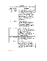
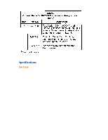
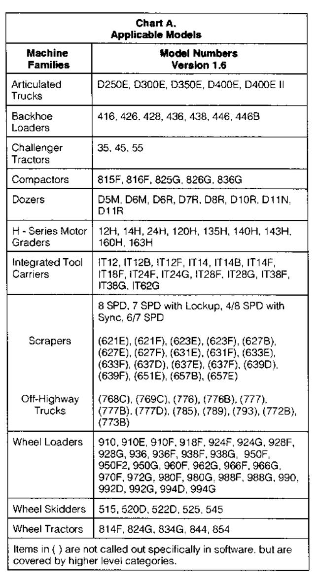
List of current machines that the 9U-7500 Transmission Analyzer II will support. Future machines will be added through the NETG5021, Annual Subscription, as they become available.
View Image
View Image
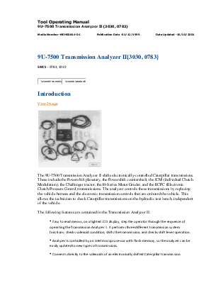
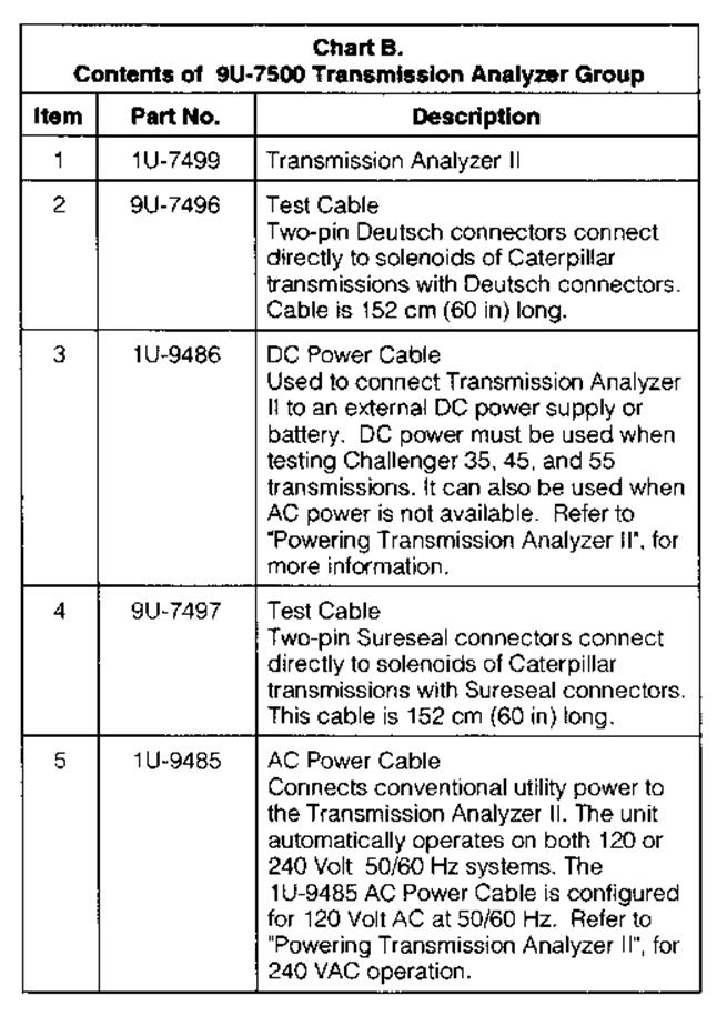
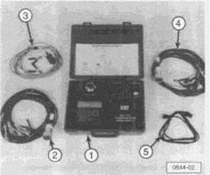 9U-7500 Transmission Analyzer
Group. Refer to Chart B for item identifications and description.
9U-7500 Transmission Analyzer
Group. Refer to Chart B for item identifications and description.
View Image
View Image
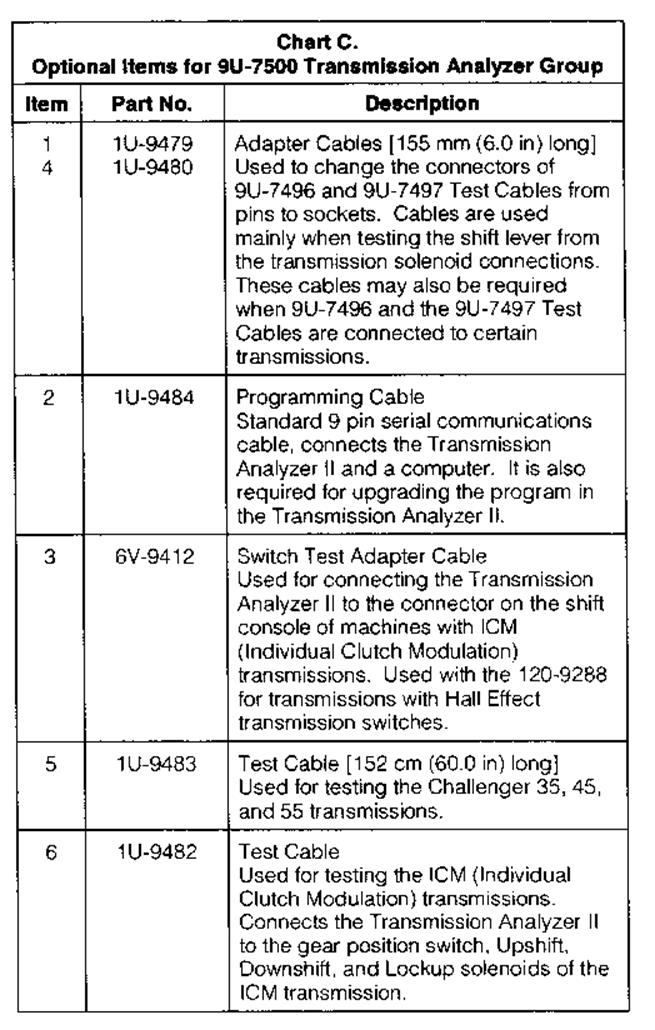
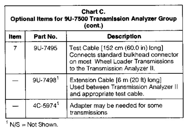
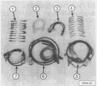 Optional parts used with the
9U-7500 Transmission Analyzer Group.
Optional parts used with the
9U-7500 Transmission Analyzer Group.
View Image
View Image
View Image
View Image
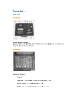
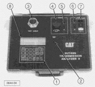 9U-7500 Transmission Analyzer.
(1) Keypad. (2) PROG PORT. (3) TEST CABLE port. (4) DC power connection. (5) DC
power switch. (6) AC power connection. (7) AC power switch. (8) Display.
9U-7500 Transmission Analyzer.
(1) Keypad. (2) PROG PORT. (3) TEST CABLE port. (4) DC power connection. (5) DC
power switch. (6) AC power connection. (7) AC power switch. (8) Display.
View Image
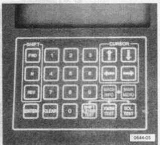 Enlarged view of keypad (1).
1. Keypad
FWD-Selects forward direction after gear number is selected.
N-Press this key to go to Neutral from any gear.
REV-Selects reverse direction after gear number is selected.
ENTER-Enters the selected command.
CLEAR-Erases a selected command or clears a fault that occurs during solenoid testing.
Cursor-These arrow keys move the cursor on the LCD screen to select the preferred menu object.
MAIN MENU-Selects a list of machine families to choose from.
MACH INFO-Selects the last machine worked on and lists descriptive data for that transmission.
SHIFT LEVER TEST-Tests shift levers on non-Autoshift transmissions.
XMSN TEST-In Transmission Test mode, shifts the transmission to any gear.
SOL TEST-In Solenoid Test mode, checks the condition of the solenoids or turns individual solenoids on one at a time.
NUMERIC KEYS-Enter the numbers asked for by the Transmission Analyzer II program, and enter the gear numbers when shifting.
2. PROG PORT
Plug serial communication cable into connector to program Flash memory.
3. TEST CABLE
Transmission test cable is plugged into this connector.
4. DC POWER
External DC power cable installs in this connector when using battery power or some other external DC power source.
5. DC Power Switch
Turns DC power ON and OFF and protects against DC power overloads.
6. AC POWER
External AC power cable is to be plugged into this connector when using utility power to power analyzer.
7. AC POWER SWITCH
Turns AC power ON and OFF and protects against AC power overloads.
8. DISPLAY
Four line/20 Character LCD display.
To adjust the contrast of the LCD display:
1. Press the up and down arrow keys at the same time.
2. This screen will appear:
View Image

3. Adjust the contrast to the desired level.
4. Press the "ENTER" key, to return to normal operation.
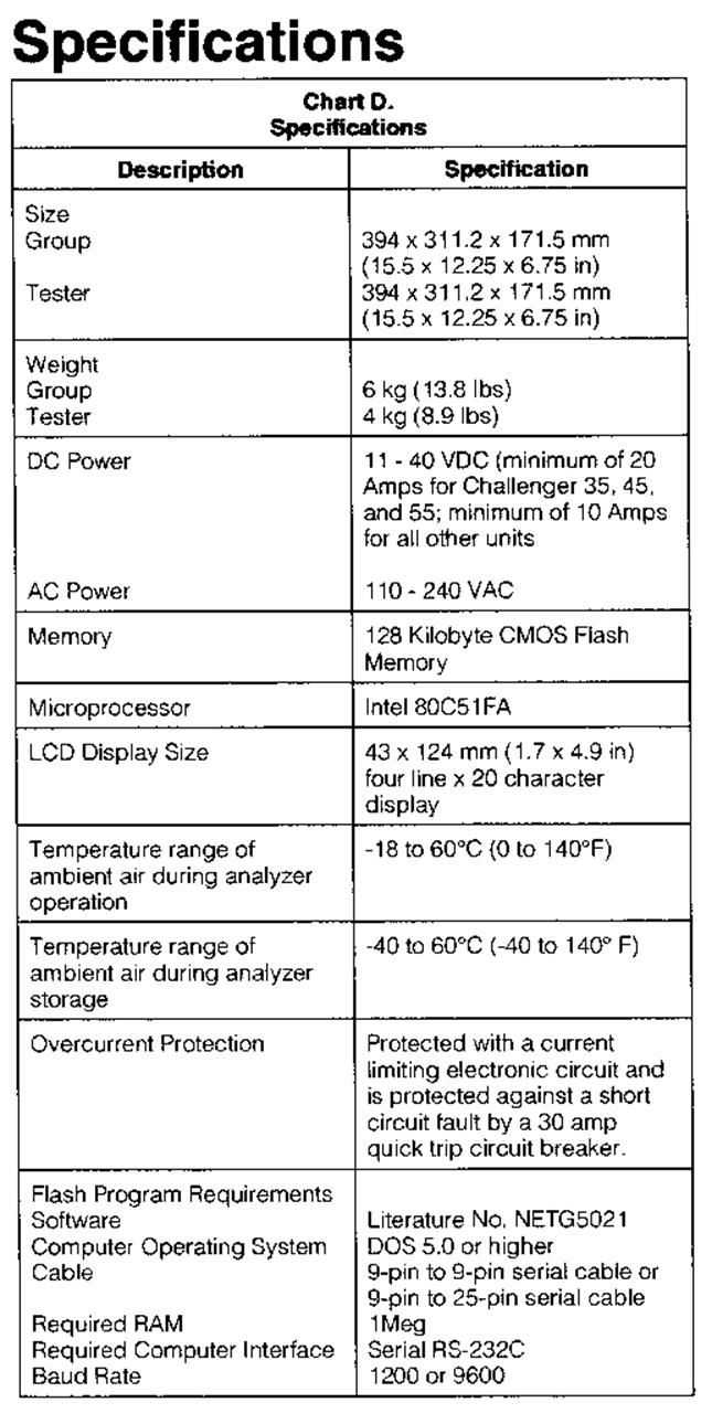
Operating on 240 Volts AC
The 9U-7500 Transmission Analyzer II can be powered from either 110 or 240 VAC 50/60 Hz. It comes from the factory with a line cord which has a U.S. 120 VAC, 60 Hz plug. To power it with 240 Volt AC, remove (cut-off) the 120 Volt AC plug and install a new 240 Volt AC plug.
Power Requirements for Challenger Transmissions
The Challenger 35, 45, and 55 Tractors need more power to operate their solenoids than other Caterpillar transmissions. To use the 9U-7500 Transmission Analyzer II on these transmissions, a larger power source must be supplied to the Analyzer.
Two different DC power sources are available for the transmission analyzer. First, a 12 Volt battery and the DC power connection with the DC power cable supplied with the unit can be used. Second, a DC power supply with filtered output that is capable
Уважаемый посетитель!
Чтобы распечатать файл, скачайте его (в формате Word).
Ссылка на скачивание - внизу страницы.