Disassembly and Assembly 784C, 785C and 785C HAA Off-Highway Truck/Tractors Power Train
|
Media Number - |
Publication Date -01/08/2004 |
Date Updated -12/08/2004 |
|
|
Differential and Bevel Gear - Disassemble
SMCS - ;
Начало формы
Disassembly Procedure
|
Table 1 |
|||
|
Required Tools |
|||
|
Tool |
Part Number |
Part Description |
Qty |
|
A |
FT-2392 |
Adjusting Nut |
1 |
|
B |
FT-2391 |
Adjusting Nut |
1 |
|
C |
5P-1730 |
Holding Fixture |
1 |
|
D |
1P-0510 |
Driver Group |
1 |
|
E |
1P-0520 |
Driver Group |
1 |
|
F |
1H-3110 |
Bearing Puller |
1 |
|
F |
1H-3107 |
Push Puller |
1 |
Start By:
|
|
|
NOTICE |
|
Care must be taken to ensure that fluids are contained during performance of inspection, maintenance, testing, adjusting and repair of the product. Be prepared to collect the fluid with suitable containers before opening any compartment or disassembling any component containing fluids. Refer to Special Publication, NENG2500, "Caterpillar Tools and Shop Products Guide" for tools and supplies suitable to collect and contain fluids on Caterpillar products. Dispose of all fluids according to local regulations and mandates. |
|
|
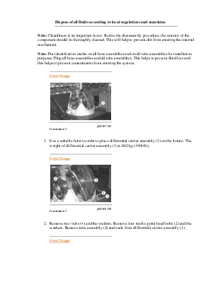
Note: Cleanliness is an important factor. Before the disassembly procedure, the exterior of the component should be thoroughly cleaned. This will help to prevent dirt from entering the internal mechanism.
Note: Put identification marks on all hose assemblies and on all tube assemblies for installation purposes. Plug all hose assemblies and all tube assemblies. This helps to prevent fluid loss and this helps to prevent contaminants from entering the system.
|
|
|
|
View Image
|
|
|
|
|
|
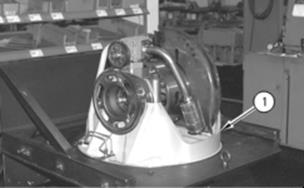
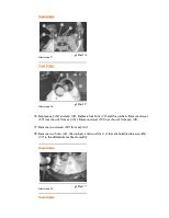
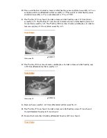
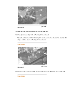
Illustration 1 |
g00567241 |
|
|
|
|
View Image
|
|
|
|
|
|
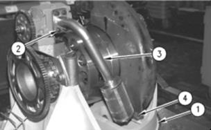
Illustration 2 |
g00565118 |
|
|
|
|
View Image
|
|
|
|
|
|
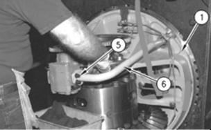
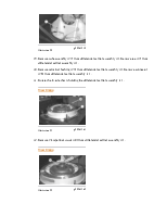
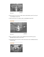
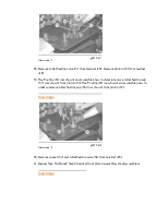
Illustration 3 |
g00565115 |
|
|
|
|
View Image
|
|
|
|
|
|
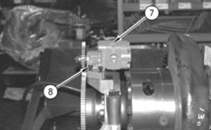
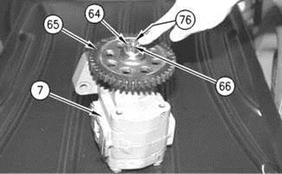
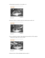
Illustration 4 |
g00564797 |
|
|
|
|
View Image
|
|
|
|
|
|
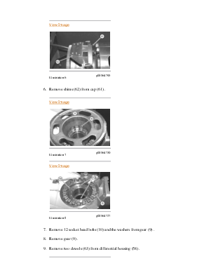
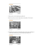
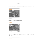
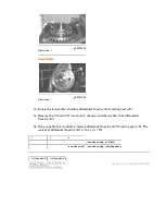
Illustration 5 |
g00564759 |
Уважаемый посетитель!
Чтобы распечатать файл, скачайте его (в формате Word).
Ссылка на скачивание - внизу страницы.