Disassembly and
Assembly
784C, 785C and 785C HAA Off-Highway Truck/Tractors Power Train
|
Media
Number --05
|
Publication Date -01/08/2004
|
Date Updated -12/08/2004
|
Transmission Planetary and
Transfer Gears - Install
SMCS
-
-012
Installation
Procedure
|
Table 1
|
|
Required Tools
|
|
Tool
|
Part Number
|
Part Description
|
Qty
|
|
A
|
6V-0006
|
Governor
Pliers
|
1
|
|
B
|
6V-3145
|
Load
Leveler
|
1
|
Note: Cleanliness is an
important factor. Before the installation procedure, all parts should be
thoroughly cleaned in cleaning fluid. Allow the parts to air dry. Wiping cloths
or rags should not be used to dry parts. Lint may be deposited on the parts
which may cause later trouble.
- Check all of the O-ring seals and the
components for wear or damage. Replace the components, if necessary.
- Lubricate all of the O-ring seals
lightly with the lubricant that is being sealed.
|
|
|
View Image
|
|
|
|
Illustration
1
|
g00568837
|
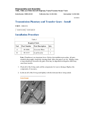
- Install Tool (B) to planetary
transmission and transfer gear (2). Attach Tool (B) to a suitable lifting
device and a hoist.
- Use Tool (B) and the hoist in order to
position planetary transmission and transfer gear (2) for installation to
the differential carrier assembly. The weight of planetary transmission
and transfer gear (2) is 2313 kg (5100 lb).
- Use 24 bolts (22) and the hard
washers in order to install planetary transmission and transfer gear (2)
and the O-ring seal to the differential carrier assembly. Tighten 24 bolts
(22) to a torque of 430 ± 60 N·m (317.15 ± 44.25 lb ft).
- Remove Tool (B) from planetary
transmission and transfer gear (2) .
|
|
|
View Image
|
|
|
|
Illustration
2
|
g00568835
|
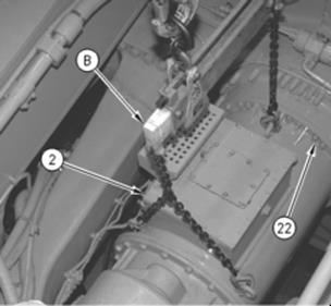
- Connect hose assembly (21) .
- Connect hose assembly (20) .
|
|
|
View Image
|
|
|
|
Illustration
3
|
g00568833
|
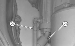
- Connect hose assembly (19) to the
magnetic screen housing.
|
|
|
View Image
|
|
|
|
Illustration
4
|
g00568770
|
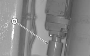
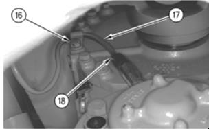
- Use Tool (A) (not shown) in order to
connect wire harness (17) to the transmission speed sensor at the
electrical connection.
- Install lockwire (18) into the
electrical connector of wire harness (17) .
Note: Install the
lockwire in the next endbell hole in the clockwise direction.
- Install bolt (16), the washer and the
clip to the transfer case assembly. Tighten bolt (16) to a torque of 135 ±
20 N·m (100 ± 15 lb ft).
|
|
|
View Image
|
|
|
|
Illustration
5
|
g00568769
|
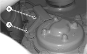
- Use two bolts (15), the washers, and
the two grommets in order to install guard (14) to the speed sensor
housing.
|
|
|
View Image
|
|
|
|
Illustration
6
|
g00567637
|
|
|
|
View Image
|
|
|
|
Illustration
7
|
g00567635
|
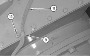
- Use bolt (13) in order to install
clip (9) .
- Connect wire harness (11) at the
three electrical connections, as shown.
|
|
|
View Image
|
|
|
|
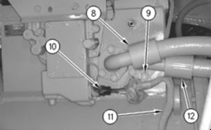
Illustration
8
|
g00567593
|
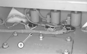
- Use Tool (A) (not shown) in order to
connect wire harness (11) to the transmission position sensor at the
electrical connection.
- Install lockwire (10) into the
electrical connection of wire harness (11) .
Note: Install the
lockwire in the next endbell hole in the clockwise direction.
- Connect hose assembly (12) and two
clips (9), as shown.
- Connect hose assembly (8) .
|
|
|
View Image
|
|
|
|
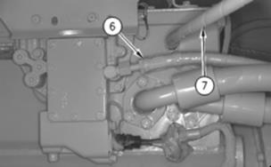
Illustration
9
|
g00567592
|
- Connect hose assembly (7) .
- Connect hose assembly (6) .
|
|
|
View Image
|
|
|
|
Illustration
10
|
g00567587
|
|
|
|
View Image
|
|
|
|
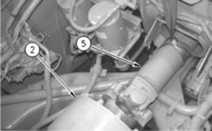
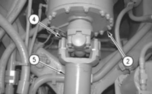
Illustration
11
|
g00567583
|
- Attach a suitable lifting sling
around drive shaft (5). Attach the lifting sling to a hoist.
Note: Attach the lifting
sling to the center point of drive shaft (5). This will help to
balance drive shaft (5) .
- Use the hoist and the lifting sling
in order to position drive shaft (5) for installation.
- Use a suitable pry bar in order to
extend drive shaft (5). Use four new bolts (4) in order to connect drive
shaft (5) to the yoke of planetary transmission and transfer gear (2).
Tighten four bolts (4) to a torque of 550 ± 20 N·m (405.7 ± 14.8 lb ft).
- Remove the lifting sling from drive
shaft (5) .
|
|
|
View Image
|
|
|
|
Illustration
12
|
g00567576
|
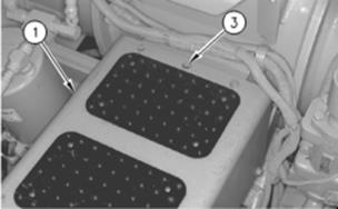
- Position guard assembly (1) onto the
frame assembly. Use five bolts (3) and the hard washers in order to
install guard assembly (1) to the frame assembly.
- Fill the differential and final drive
with hydraulic oil to the correct level. Refer to Operation and
Maintenance Manual, SEBU7173, "Differential and Final Drive Oil -
Change" for the correct procedure.
- Fill the transmission system with
hydraulic oil to the correct level. Refer to Operation and Maintenance
Manual, SEBU7173, " Transmission Tank Oil - Change" for the
correct procedure.
,,
End By:
- Remove the retaining cable. Refer to
Disassembly and AssemblySENR1500, "Body Retaining Cable - Remove and
Install".
- Remove the wheel chocks. Refer to
Disassembly and AssemblySENR1500, "Wheel Chocks (Front and Rear) -
Remove and Install".