|
Table 1 |
|||
|
Required Tools |
|||
|
Tool |
Part Number |
Part Description |
Qty |
|
A |
1P-0510 |
Driver Group |
1 |
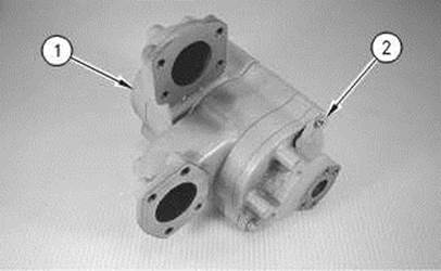
Start By:
Note: Cleanliness is an important factor. Before the disassembly procedure, the exterior of the component should be thoroughly cleaned. This will help to prevent dirt from entering the internal mechanism.
|
|
|
|
|
|
|
|
|
|
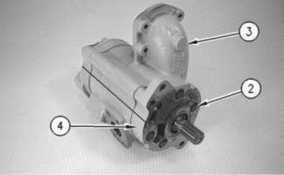
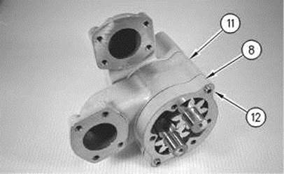
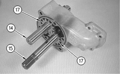
Illustration 1 |
g00527693 |
|
|
|
|
|
|
|
|
|
|
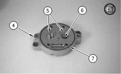
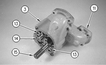
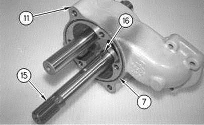
Illustration 2 |
g00527694 |
|
|
|
|
|
|
|
|
|
|
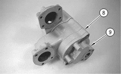
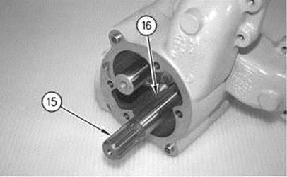
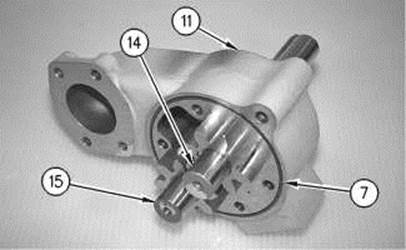
Illustration 3 |
g00527696 |
|
|
|
|
|
|
|
|
|
|
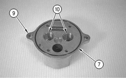
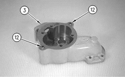
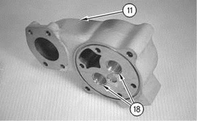
Illustration 4 |
g00527700 |
|
|
|
|
|
|
|
|
|
|
Illustration 5 |
g00527701 |
|
|
|
|
|
|
|
|
|
|
Illustration 6 |
g00527702 |
|
|
|
|
|
|
|
|
|
|
Illustration 7 |
g00527703 |
|
|
|
|
|
|
|
|
|
|
Illustration 8 |
g00527704 |
|
|
|
|
|
|
|
|
|
|
Illustration 9 |
g00527705 |
|
|
|
|
|
|
|
|
|
|
Illustration 10 |
g00527706 |
|
|
|
|
|
|
|
|
|
|
Illustration 11 |
g00527707 |
|
|
|
|
|
|
|
|
|
|
Illustration 12 |
g00527708 |
|
|
|
|
|
|
|
|
|
|
Illustration 13 |
g00527709 |
Уважаемый посетитель!
Чтобы распечатать файл, скачайте его (в формате Word).
Ссылка на скачивание - внизу страницы.