

PS-Estimator is included as part of the basic PowerSHAPE module. It uses some of the functionality of PS_Draft enabling the creation of simple drawings including, cross sections, dimensions, and text. It will only allow you to save drafting items up to a limit of 100 items.
To be able to generate fully dimensioned and detailed 2D drawings from a 3D model it will be necessary to purchase the PS-Draft, Drafting module along with the associated training course.
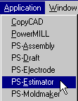
PS-Estimator is accessed through the Application menu or by selecting the PS-Draft switch
![]()
![]()
This opens the Estimator toolbar. The first 6 icons are the same as PowerSHAPE and the other icons cover text, dimensions, cross hatch, symbols, balloons, drawings and drawing views. Note some icons not available in the PS-Estimator and are greyed out.
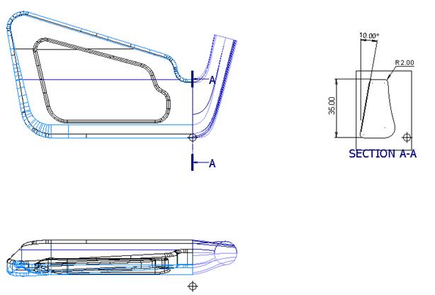
In this example we will create a few views of the golf club head model followed by a few simple dimensions.
· Open the model golf-fin
·
![]() Delete
all the wireframe.
Delete
all the wireframe.
· Select Enter/Leave Drafting
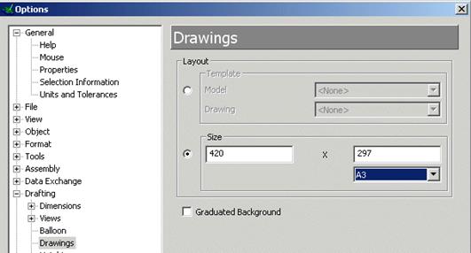
· Select Tools > Options> Drafting > Drawings and set sheet size as A3.
·
![]() Select Accept. Select create Drawing
Select Accept. Select create Drawing
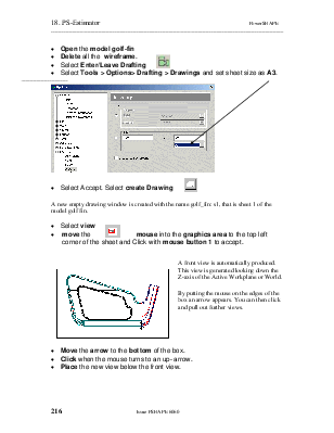
A new empty drawing window is created with the name golf_fin: s1, that is sheet 1 of the model golf fin.
![]()
· Select view
· move the mouse into the graphics area to the top left corner of the sheet and Click with mouse button 1 to accept.
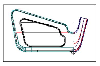 A front view is automatically produced. This view is generated
looking down the Z-axis of the Active Workplane or World.
A front view is automatically produced. This view is generated
looking down the Z-axis of the Active Workplane or World.
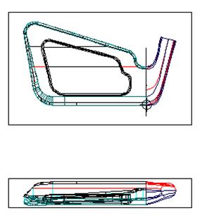
By putting the mouse on the edges of the box an arrow appears. You can then click and pull out further views.
· Move the arrow to the bottom of the box.
· Click when the mouse turns to an up- arrow.
· Place the new view below the front view.
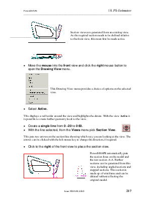
Section views are generated from an existing view. As the required section needs to be defined relative to the front view, this must first be made active.
· Move the mouse into the front view and click the right mouse button to open the Drawing View menu.
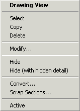
This Drawing View menu provides a choice of options on the selected view.
· Select Active.
This displays a red border around the view and highlights the datum. With the view Active it is possible to create further geometry local to the view.
·
 Create a single line from 0
–20 to 0 60.
Create a single line from 0
–20 to 0 60.
· With the line selected, from the Views menu pick Section View.
This puts two arrows on the section line showing which way you are looking at the view. The arrows can be clicked with the left mouse key to change the direction, if required.
· Click to the right of the front view to place the section view.
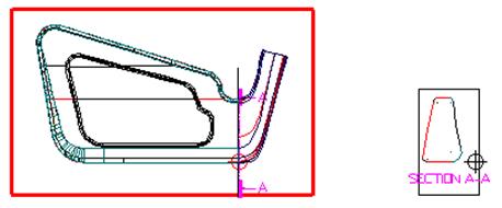 PowerSHAPE automatically puts the section lines on the model and the
text section A-A. Further sections can be generated from this view, including
angled sections and stepped sections. This section is made up of wireframe and
can be deleted without affecting theoriginal model.
PowerSHAPE automatically puts the section lines on the model and the
text section A-A. Further sections can be generated from this view, including
angled sections and stepped sections. This section is made up of wireframe and
can be deleted without affecting theoriginal model.
·
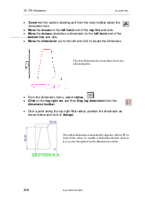
![]() Zoom into
the section drawing and from the main toolbar select the dimension icon.
Zoom into
the section drawing and from the main toolbar select the dimension icon.
· Move the mouse to the left hand end of the top line and click.
· Move the mouse (stretches a dimension) to the left hand end of the bottom line and click.
· Move the dimension out to the left and click to locate the dimension.
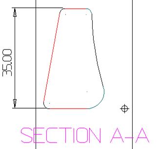
The first dimension has been taken from two selected points.
![]()
·
![]() From the dimension menu, select radius.
From the dimension menu, select radius.
· Click on the top right arc and then Dog leg dimension from the dimension toolbar.
· Click a point along the top right fillet radius, position the dimension as shown below and click to Accept.
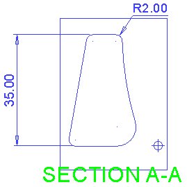
The radius dimension automatically appears with an 'R' in front of the value. To modify a dimension double-click on it to access the options in the dimensions toolbar.
·
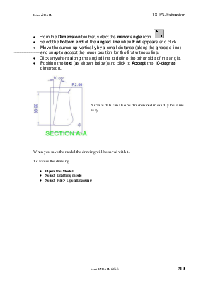
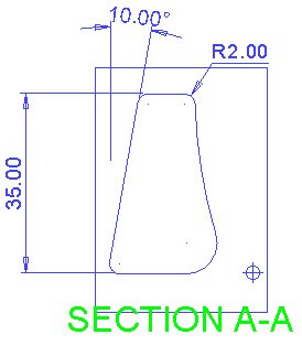
From the Dimension toolbar, select the minor
angle icon. ![]()
· Select the bottom end of the angled line when End appears and click.
· Move the cursor up vertically by a small distance (along the ghosted line) and snap to accept the lower position for the first witness line.
· Click anywhere along the angled line to define the other side of the angle.
· Position the text (as shown below) and click to Accept the 10-degree dimension.
Surface data can also be dimensioned in exactly the same way.
When you save the model the drawing will be saved with it.
To access the drawing
· Open the Model
· Select Drafting mode
· Select File> Open Drawing
Уважаемый посетитель!
Чтобы распечатать файл, скачайте его (в формате Word).
Ссылка на скачивание - внизу страницы.