An option exists to specify the position of some types of feature with respect to the solid by using the Solid Feature Relationship dialog box. Relationships can be created for solid cut, solid boss, Boolean, Boolean-boss and hole features and are defined by selecting a key point on the solid, a key point on the feature and specifying a distance between the two.
· Open a new model.
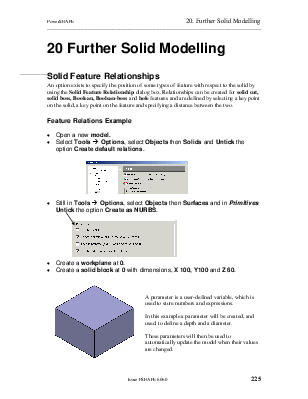
· Select Tools è Options, select Objects then Solids and Untick the option Create default relations.
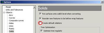
· ![]() Still in
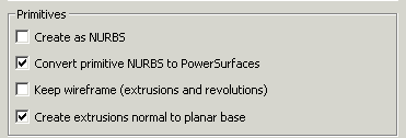
Tools è Options, select Objects then Surfaces and in Primitives
Untick the option Create as NURBS.
Still in
Tools è Options, select Objects then Surfaces and in Primitives
Untick the option Create as NURBS.
· Create a workplane at 0.
· Create a solid block at 0 with dimensions, X 100, Y100 and Z 60.
A parameter is a user-defined variable, which is used to store numbers and expressions.
In this example a parameter will be created, and used, to define a depth and a diameter.
These parameters will then be used to automatically update the model when their values are changed.
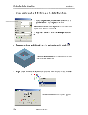
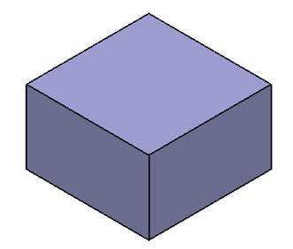
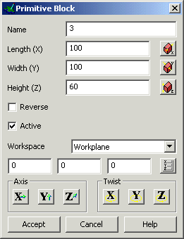
· Create a solid block at 0, 0, 60 and open the Solid Block form.
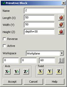
· Set a length of 50, width of 50 and create a parameter for the height as shown.
A Parameter with the name depth will be created with an expression or numeric value of 30.
· Apply a Y twist of 180° and Accept the form.
![]()
· Remove the inner solid block from
the main outer solid block. ![]()

A Feature Relationship will be set between the inner feature and the outer block.
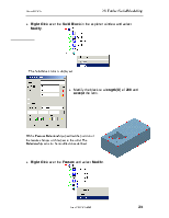
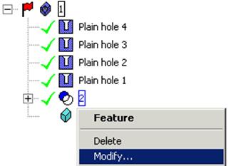
· Right Click over the Feature in the explorer window and select Modify.
![]()
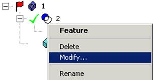
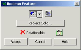
The Boolean Feature editing form appears.
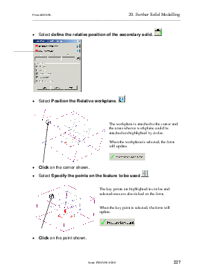
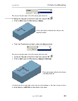
· Select define the relative position of the secondary solid. ![]()
· Select Position the Relative workplane. ![]()
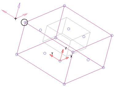
![]() The workplane is attached to the cursor and the areas where a
workplane could be attached are highlighted by circles.
The workplane is attached to the cursor and the areas where a
workplane could be attached are highlighted by circles.
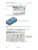
When the workplane is selected, the form will update.
![]()
· Click on the corner shown.
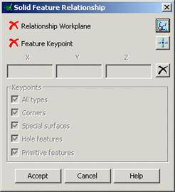
· Select Specify the points on the feature to be used ![]() .
.
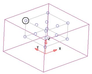
 The key points are highlighted in circles and selected ones are also
ticked on the form.
The key points are highlighted in circles and selected ones are also
ticked on the form.
When the key point is selected, the form will update.
![]()
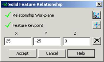
· Click on the point shown.
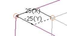
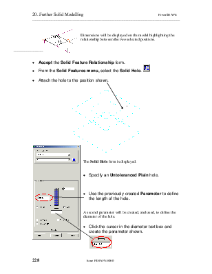
Dimensions will be displayed on the model highlighting the relationship between the two selected positions.
· Accept the Solid Feature Relationship form.
· From the Solid Features menu, selectthe Solid Hole.
![]()
· Attach the hole to the position shown.
 |
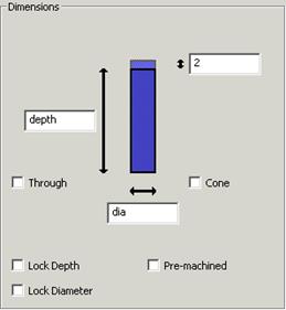
The Solid Hole form is displayed.
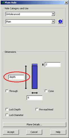
· Specify an Untoleranced Plain hole.
· ![]() Use the
previously created Parameter to define the length of the hole.
Use the
previously created Parameter to define the length of the hole.
 A second parameter will be created, and used, to define the diameter
of the hole.
A second parameter will be created, and used, to define the diameter
of the hole.
· 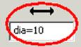 Click the cursor in the diameter text box and create
the parameter shown.
Click the cursor in the diameter text box and create
the parameter shown.
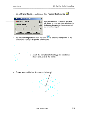
· Select Plane Details…. button and then Feature
Relationship ![]()
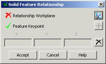
With Hole Features the Feature Keypoint will always be the origin of the hole, therefore the Feature Keypoint has been pre-selected and cannot be changed.
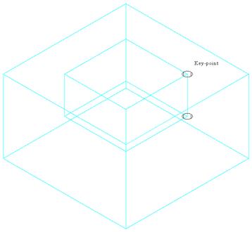
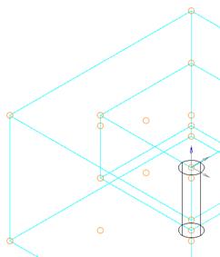
· Select the workplane icon on the form ![]() to attach a workplane
to the cursor and display key points on the solid.
to attach a workplane
to the cursor and display key points on the solid.
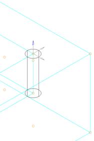
· Attach the workplane to the key point position as shown and Accept the forms.
· 
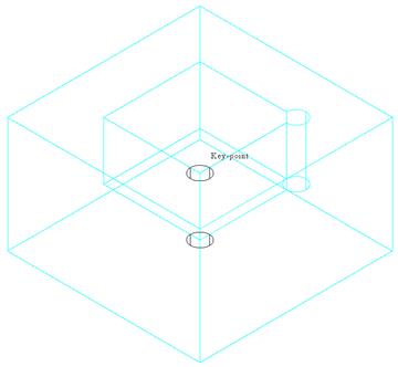 Create a second hole at the position indicated.
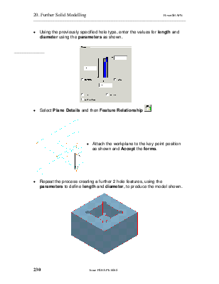
· Using the previously specified hole type, enter the values for length and diameter using the parameters as shown.
· Select Plane Details and then Feature Relationship ![]()
· Attach the workplane to the key point position as shown and Accept the forms.
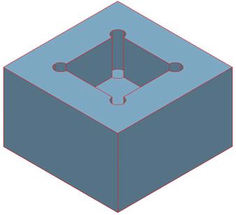
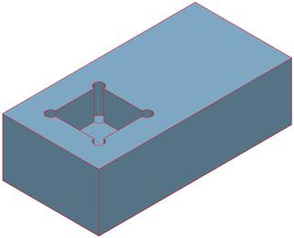
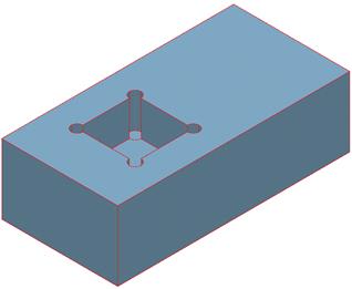
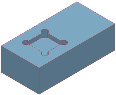
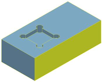
· Repeat the process creating a further 2 hole features, using the parameters to define length and diameter, to produce the model shown.
·  Right Click over the Solid
Block in the explorer window and select Modify.
Right Click over the Solid
Block in the explorer window and select Modify.
The Solid Block form is displayed.
· Modify the block to a length (X) of 200 and accept the form.
With a Feature Relationship specified the position of the feature changes with respect to the solid. The Relationship can also be modified once defined.
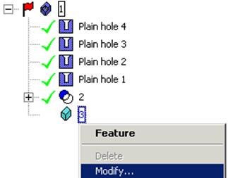
· Right Click over the Feature and select Modify.
· Select the Feature Relationship icon ![]() to open the form.
to open the form.
· Enter an X value of 40 and Accept the form.
The position of the feature is modified.
The Parameters created defining depth and diameter can also be modified to change the feature.
· From the Object pull down menu at the top of the screen, select the Parameter option to open the Parameter Editor form.
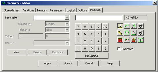

The Parameter Editor allows parameters to be created and modified.
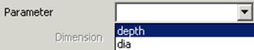
· From the Parameter pull down select the depth parameter.
The value of the parameter (30) will be displayed in the form.
· Using the Keypad on the form clear the value of 30.![]()
·  Enter a new value of 10 and press Apply.
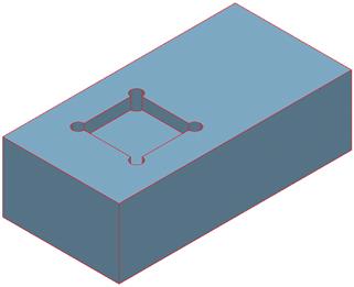
The model updates reflecting the change to the depth parameter.
· From the Parameter pull down select the dia parameter.
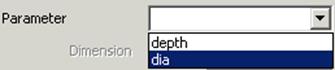
The value of the parameter (10) will be displayed in the form.
· Using the Keypad on the form clear the value of 10.![]()
· Enter a new value of 15 and press Apply and Accept.
The model updates reflecting the change to the dia parameter.
An important point to remember when working with parameters is that they are case sensitive i.e. depth, Depth and DEPTH are three different parameters.
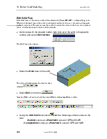
Individual faces of the active solid can be edited using PowerSHAPE’s surface editing tools. When an individual face of the solid is selected for editing in this way, the main surface edits toolbar is activated. The user can use the toolbar to add extra curves to the face, move picked points, and change tangent angles and magnitudes.
· 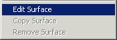 Continuing with the created model, right click over
the solid in the graphic window and select Edit Surface.
Continuing with the created model, right click over
the solid in the graphic window and select Edit Surface.
The Edit Face form appears.
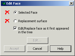
· Select the front face of the solid.
 |
The form will indicate that the face has
been selected.![]()
· Select Edit on the form.![]()
Selecting Edit will activate both the general Edit and Surface Edits toolbars.
![]()
![]()
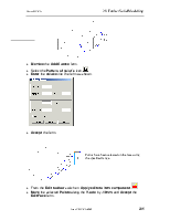
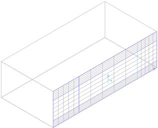
· Using the Add Curve command![]() add the following surface
curves to the face.
add the following surface
curves to the face.
2 Lateral curves at a Parametric value of 1.75 and 1.25
2 Longitudinal curves at a Parametric value of 1.75 and 1.25
· Dismiss the Add Curves form.
· Select the Pattern of point’s icon.![]()
· Enter the values into the form as shown.
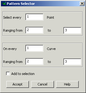
· Accept the form.
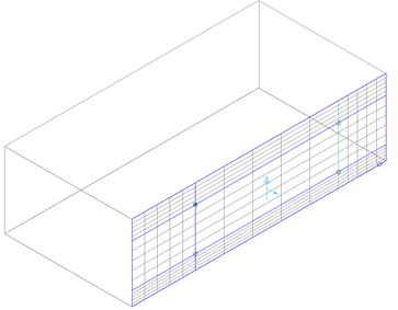
Points have been selected on the face using the specified range.
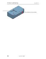
· From the Edit toolbar switch on Apply edits to item
component. ![]()
· Move the selected Points along the Y-axis by -10mm and Accept the Edit Face form.
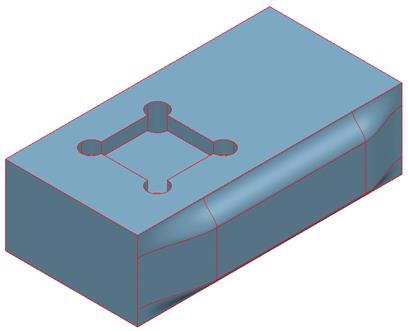
The solid face has been modified.
Уважаемый посетитель!
Чтобы распечатать файл, скачайте его (в формате Word).
Ссылка на скачивание - внизу страницы.