Basic shading is displayed by clicking the various icons in the View Toolbar. It will shade all of the surfaces that are displayed in the same material. As surfaces have an inside and outside the outside is displayed in a blue colour and the inside as red.
· Open the model golf-fin. Activate workplane 2 and
select view ISO 4. ![]()
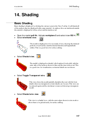
· ![]() Select wireframe view.
Select wireframe view.
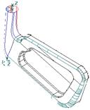
The model is displayed as if it was made of wire, showing the trimmed portions of each surface and the internal laterals and longitudinals within. This is a good view for surface editing.
![]()
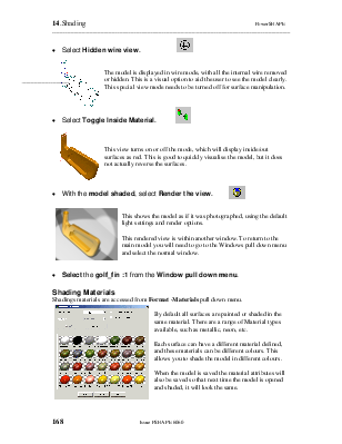
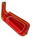
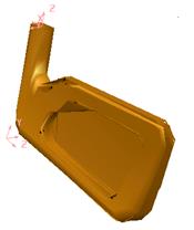
· Select Shaded view.
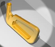
The model is displayed as shaded, which makes it look solid, with the outer side of the surfaces shown in blue and the inner side as red. This is a good view for visualisation, as internal details are not shown.
![]()
· Select Toggle Transparent wire.
This view shows the model partially shaded at the rear with the front details shown as transparent so inner details can be seen. This view can be selected again and the wireframe is removed, showing a transparent model.
![]()
· Select Shaded wire view.
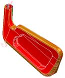
This view is a shaded view, with the outer edges shown in wire mode to allow them to be picked easily for surface editing.
![]()
· Select Hidden wire view.
The model is displayed in wire mode, with all the internal wire removed or hidden. This is a visual option to aid the user to see the model clearly. This special view mode needs to be turned off for surface manipulation.

· Select Toggle Inside Material.
This view turns on or off the mode, which will display inside/out surfaces as red. This is good to quickly visualise the model, but it does not actually reverse the surfaces.
![]()
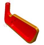
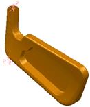
· With the model shaded, select Render the view.
This shows the model as if it was photographed, using the default light settings and render options.
This rendered view is within another window. To return to the main model you will need to go to the Windows pull down menu and select the normal window.
· Select the golf_fin :1 from the Window pull down menu.
 Shadings
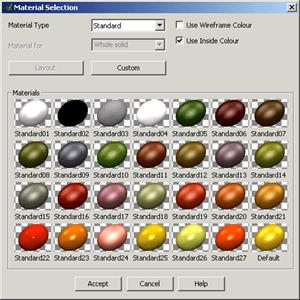
materials are accessed from Format -Materials pull down menu.
Shadings
materials are accessed from Format -Materials pull down menu.
By default all surfaces are painted or shaded in the same material. There are a range of Material types available, such as metallic, neon, etc.
Each surface can have a different material defined, and these materials can be different colours. This allows you to shade the model in different colours.
When the model is saved the material attributes will also be saved so that next time the model is opened and shaded, it will look the same.
To change the material of a selected surface(s):
1. Ensure that shaded images are displayed
2. Select a surface or group of surfaces.
3. Raise the Materials dialogue box and select a new material.
To change the default material:
1. Ensure that no surface is selected.
2. Raise the Materials dialogue box and select a new material.
3. Click Accept and the new material will be used for subsequent surface colour shading.
· Change the materials on each surface of your model to different colours.
Each material can be altered to your own specifications.
· Select Format -Materials form, select Spring and pick Spring13.
· Select the option Custom.
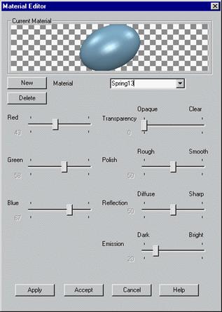
The materials Editor form appears. This form allows the appearance of the shading effect to be altered using various sliders.
· Select New. Leave the name as Spring13copy.
· Alter the slides to see the effect at the top. Apply the form.
· Select any surface and the material is changed to the new one.
When models are shaded, the whole surface is covered in a triangular mesh, which is set at a certain tolerance i.e. the smaller the value, the finer the mesh. These values are found under the Shading Option, found under options in the Tools pull down menu.
· Select Tools è Options and from View, select Shading.
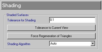 Tolerance to current view is a quick way
of entering the ideal value for your particular screen resolution and current
zoom. PowerSHAPE will use the new tolerance the next time the shading is regenerated.
If you want to see it immediately, click the button, Force regeneration of
triangles.
Tolerance to current view is a quick way
of entering the ideal value for your particular screen resolution and current
zoom. PowerSHAPE will use the new tolerance the next time the shading is regenerated.
If you want to see it immediately, click the button, Force regeneration of
triangles.
· Set the Tolerance for Shading to 5
· Press Force Regeneration of triangles. Press Accept.
The model is shown very faceted. Although, if you change to wireframe view the model still looks normal. For small models the shading tolerance should be reduced.
· Open the Options form and set the shading tolerance to 0.1.
Уважаемый посетитель!
Чтобы распечатать файл, скачайте его (в формате Word).
Ссылка на скачивание - внизу страницы.