3 ALU INSTRUCTIONS
Figure 3-0.
Table 3-0.
Listing 3-0.
The instruction set provides ALU instructions for performing arithmetic and logical operations on 16- and 24-bit fixed-point data. ALU instructions include:
• “Add/Add with Carry” on page 3-5
• “Subtract X-Y/Subtract X-Y with Borrow” on page 3-8
• “Subtract Y-X/Subtract Y-X with Borrow” on page 3-12
• “Bitwise Logic: AND, OR, XOR” on page 3-15
• “Bit Manipulation: TSTBIT, SETBIT, CLRBIT, TGLBIT” on page 3-18
• “Clear: PASS” on page 3-20
• “Negate: NOT” on page 3-23
• “Absolute Value: ABS” on page 3-26
• “Increment” on page 3-29
• “Decrement” on page 3-32
• “Divide Primitives: DIVS and DIVQ” on page 3-35
• “Generate ALU Status Only: NONE” on page 3-44
This chapter describes each of the arithmetic instructions and the following related topics:
• “Input Registers” on page 3-2
• “Output Registers” on page 3-2
• “Constants” on page 3-3
• “ALU Mode Control” on page 3-4
• “ALU Status Flags” on page 3-4
The unconditional single-function ALU instructions described in this chapter can use any of the DSP’s sixteen data registers, referred to as Dregs, as input operands. The conditional single-function ALU instructions are restricted to the use of specific data registers for both the x and y input operands. When restrictions apply, Xop refers to the x operand, and Yop refers to the y operand.
ALU instructions use one of two output registers:
• AF ALU feedback register
Results are directly available for the y input only in the next conditional ALU operation.
• AR ALU result register
Results output to this register are immediately available as the x-input only in the next conditional ALU, MAC, or shifter operation or as either x or y input into the next unconditional ALU, MAC, or shifter operation.
Constants
You can use constants in any of the following single-function ALU instructions:
• Add operations
• Subtract operations
• Bitwise logic operations
• PASS operation
Valid constants are those formed from powers of two and that fall within the range of −32768 (0x8000) and +32767 (0x7FFF). Table 3-1 lists the valid constants.
Table 3-1. Valid constant values
|
Positive (+) |
Neg |
ative (−) |
|
|
Decimal |
Hexadecimal |
Decimal |
Hexadecimal |
|
1 |
0x0001 |
2 |
0xFFFE |
|
2 |
0x0002 |
3 |
0xFFFD |
|
4 |
0x0004 |
5 |
0xFFFB |
|
8 |
0x0008 |
9 |
0xFFF7 |
|
16 |
0x0010 |
17 |
0xFFEF |
|
32 |
0x0020 |
33 |
0xFFDF |
|
64 |
0x0040 |
65 |
0xFFBF |
|
128 |
0x0080 |
129 |
0xFF7F |
|
256 |
0x0100 |
257 |
0xFEFF |
Table 3-1. Valid constant values (Cont’d)
|
Positive (+) |
Neg |
ative (−) |
|
|
Decimal |
Hexadecimal |
Decimal |
Hexadecimal |
|
512 |
0x0200 |
513 |
0xFDFF |
|
1024 |
0x0400 |
1025 |
0xFBFF |
|
2048 |
0x0800 |
2049 |
0xF7FF |
|
4096 |
0x1000 |
4097 |
0xEFFF |
|
8192 |
0x2000 |
8193 |
0xDFFF |
|
16384 |
0x4000 |
16385 |
0xBFFF |
|
32767 |
0x7FFF |
32768 |
0x8000 |
The AV_LATCH and AR_SAT bits MSTAT register enable and disable two ALU modes: ALU overflow latch mode and ALU saturation mode. For more information on these modes, see the bit descriptions in Table 2-6 on page 2-11.
The AZ, AN, AV, AC, AS, and AQ bits ASTAT register record the status from ALU operations, indicating whether the result of the operation equals zero, was negative, overflowed, carried, was signed, or produced a quotient. For more information on these modes, see the bit descriptions in Table 2-2 on page 2-5.
Add/Add with Carry
![]()
![]()
![]() = DREG1 +DREG2;
= DREG1 +DREG2;
DREG + C
C
[IF COND]= XOP +YOP;
YOP + C
C constant
constant + C
Adds the input operands and stores the result in the specified result register.
If execution is based on a condition, the ALU performs the addition only if the condition evaluates true, and it performs a NOP operation if the condition evaluates false.
For the unconditional form of this instruction, you can use any of these data registers for the DREG inputs:
|
Register File |
|
AX0, AX1, AY0, AY1, AR, MX0, MX1, MY0, MY1, MR0, MR1, MR2, SR0, SR1, SR2, SI |
For the conditional form of this instruction, the input operands are restricted. Valid XOP and YOP registers are:
|
Xops |
Yops |
|
AX0, AX1, AR, MR0, MR1, MR2, SR0, SR1 |
AY0, AY1, AF, 0 |
AR ALU result register. Results are directly available for x input only in the next conditional ALU, MAC, or shifter operation or as either x or y input in the next unconditional ALU, MAC, or shifter operation.
AF ALU feedback register. Results are directly available for the y input only in the next conditional ALU operation. STATUSFLAGS
|
Affected Flags–set or cleared by the operation |
Unaffected Flags |
|
AZ, AN, AV, AC |
AS, AQ, MV, SS, SV |
|
For information on these status bits in the ASTAT register, see Table 2-2 on page 2-5. |
|
Omitting the condition forces unconditional execution of the instruction. This instruction uses binary addition to add the x and y operands and the carry bit, when specified.
The operands are stored in the data registers, or, in the case of constants, supplied in the instruction. For the conditional form of this instruction, data registers are restricted.
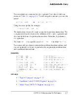
Add/Add with Carry
You can substitute a constant for the y operand. For a list of valid constants, see Table 3-1 on page 3-3. To add a negative constant, you use this syntax:
AR = AR − 4097; or AR = AR + 0xEFFF; Using the carry option, for example:
Уважаемый посетитель!
Чтобы распечатать файл, скачайте его (в формате Word).
Ссылка на скачивание - внизу страницы.