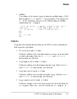
Although the DO UNTIL instruction uses the CE syntax only, the condition actually tested is NOTCE—counter not expired.
To use a counter condition with either instruction type, you must load the CNTR register with an initial counter value (>1) before issuing the instruction that uses the counter condition.
There are some important differences between how conditional and loop instructions implement (decrement and test) the counter condition:
• To implement the NOT CE condition in an IF Condition (conditional) instruction, the DSP decrements and tests the value loaded in the CNTR register before executing the conditional instruction. For a conditional instruction based on NOT CE, the DSP tests whether the CNTR register contains a value >1.
• To implement the CE condition in a DO UNTIL (loop) instruction, the DSP loads the loop counter stack from the CNTR register at the start of the loop, then decrements and tests the counter value in the loop counter stack (not the CNTR register) at the end of each pass through the loop. For a loop instruction based on CE, the DSP tests whether the loop counter stack’s counter value >0. For more information, see “Loop Stacks Operation” on page 8-10.
Table 2-3 on page 2-7 lists the CCODE register values used to test the
SWCOND and NOT SWCOND software conditions. Although the source each value tests is specific to each DSP in the ADSP-219x family, these values (except 0x08 and 0x09) map to the software interrupt bits in the IMASK and IRPTL registers.
To test for any software condition, first load the CCODE register with the value of the source you want to test, then test for the true or false state. For example, 0x08 represents ALU saturation status, you might code this sequence:
CCODE = 0x08; /* ALU Saturated (AR_SAT) cond */
AR = AX0 + AY1;
IF SWCOND JUMP fix_data; /* Jump to fix_data if AR_SAT */
fix_data:
NOP; /* code to fix data ALU_SAT */ Or, to test for a shifter overflowed result:
CCODE = 0x09; /* Shifter Overflowed (SV) cond */
AR = 3; SE = AR; /* shift code, left shift 3 bits */
SI = 0xB6A3; /* value of hi word of input data */ IF NOT SWCOND SR = ASHIFT SI (HI); /* ashift high word if SV */
A value written to CCODE isn’t available on the next cycle, so you must insert at least one instruction between the write to CCODE and the conditional instruction that tests the software condition. Otherwise, the conditional instruction will test the previous value of CCODE.
As shown in Table 2-6 on page 2-11, bits 0 through 7 of the MSTAT register control various DSP modes. These modes determine some conditions for how status flags are set.
Branch Options
All of the DSP’s branch instructions (except DO UNTIL and LJUMP/LCALL), support two branch options: immediate and delayed. These options determine whether the DSP executes the first two instructions directly following the branch instruction before it executes the instruction at the branch target address. Because of the instruction pipeline, a number of latency cycles (usually four) occur between execution of the branch instruction and execution of the branch target instruction.
By default, the branch instructions perform an immediate branch, which means that the next instruction the DSP executes after the branch instruction is the instruction at the branch target address, but only after a number of NOP cycles. Using the delayed option, you can salvage two of the NOP cycles and perform useful work. To do so, you include the (DB) option in the branch instruction and code in the two delay slots directly following the branch instruction the two instructions that you want executed before the branch target instruction.
|
! |
You cannot insert JUMP or CALL instructions in delay branch slots. You can insert only one two-word instruction, and it must occupy the first delay branch slot.
When the DSP executes an RTI or RTS instruction to return to the main program, it returns to execute the first or third instruction after the branch instruction, depending on whether the branch is immediate or delayed.
Return from immediate branch:
IF AV CALL immediate_pump; /* immed branches may be cond */
NOP; /* RTS returns program flow here */ NOP;
immediate_pump:
NOP;
RTS;
Return from delayed branch:
CALL delayed_pump (DB); /* delayed branches must be uncond */
NOP; /* 1st_delay_instruction */
NOP; /* 2nd_delay_instruction */
NOP; /* RTS returns program flow here */ NOP;
delayed_pump:
NOP;
RTS;
When you issue a JUMP or CALL instruction, you specify the address of the instruction to branch to in one of three ways:
• PC relative
Offset from the current PC. The immediate value you specify in the instruction is added to the PC of the branch instruction to form the address of the branch target location. For example, the CALL in the following code goes to PC-relative
Уважаемый посетитель!
Чтобы распечатать файл, скачайте его (в формате Word).
Ссылка на скачивание - внизу страницы.