|
OVERVIEW |
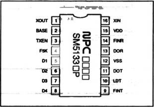
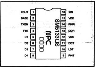
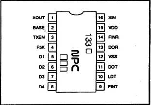
PINOUTS |
|
SM5133 sa•ies are CMOS ISIS that incorporate |
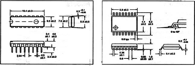
16-pin DIP |
 The SM5133E feattres 15
 ![]() channels md the SM5133D feattres 10
communication chanœls. SM5133 feature parallel cornrrnmk:ún
channels md the SM5133D feattres 10
communication chanœls. SM5133 feature parallel cornrrnmk:ún
SM5133 series fran a 24 to 5.5 V supply available in 16-pin DIPS, SOPs ssops.
• Transmit and receive PLLs
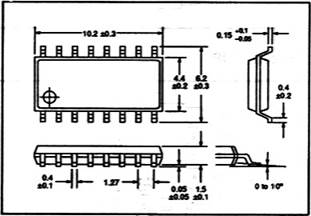
• Baseset unit handset unit selection 16-pin SOP
•
 10 chanœls
(SM5133D) 15 commtmication channels (SM5133E)
10 chanœls
(SM5133D) 15 commtmication channels (SM5133E)
• channel selection
• Built-in digital lock
•
![]() Standby suspends
trmsnit to save
Standby suspends
trmsnit to save
• MHz maximum operating
• Direct freque1EY divisim locking in transmit
PLL at 46 49 MHz freqœncy
• 300 mVp, (min) input sensitivity
• 5 kHz refa•ence freqœrEY
•
![]() CMOS
CMOS
• 2.4 to 5.5 V suM)ly
• 16-pin plastic DIP, SOP and SSOP
16-pin SSOP
|
|
|
||
|
10 |
|
||
|
16*' sop |
|||
|
ssœ |
|||
|
15 |
|||
PRECISn•
133
Unit nun
 |
16-pin sop
|
Number |
Name |
DescrÞtion |
|
|
1 |
XOUT |
CrysäJ osal!aw Aso comecbd b rtfxer |
|
|
2 |
Basesethnndset unit selea hp.it mode LOW baseset mode I-OGH htemal ræsto« |
||
|
3 |
Transmit
|
||
|
4 |
5 |
||
|
5 b 8 |
DI b |
muniäion chard sdect parahd dab irŽBJt |
|
|
9 |
ræMit
hput |
||
|
10 |
LDT |
a.:tPJt HIGH unbcked (ransnit |
|
|
11 |
DOT |
ransmit pæsive fitter comætm |
|
|
12 |
|||
|
13 |
pæsive fitter |
||
|
14 |
Receive
programm& dMder inwt hterral |
||
|
15 |
24 b 55 V |
||
|
16 |
C'y•su oscillator and c•y'ectbn. Éedbd resistance |
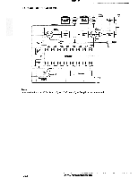
BLOCK DIAGRAM
TXEN
PIN DESCRIPTION
Absolute Maximum Ratings
Recommended Operating Conditions
T. = 25 deg. C
|
Parameter |
Symbol |
Rathg |
Unit |
|
rarge |
Voo |
24 b 5.5 |
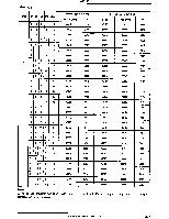
Electrical Characteristics
|
Symbol |
Rathg |
Unit |
|
|
|
VDO — Vs |
-0.3 b 7.0 |
|
|
rarve |
Vs b Voo |
||
|
bmgaure rav |
-40 b 16 |
deg. C |
|
|
|
|
deg C |
|
|
10 |
s |
VDD = 2.4 to 5.5 V, vss = O V , T![]() =
—30 to 80 deg.
=
—30 to 80 deg. ![]()
|
Parameter |
Symbol |
Condition |
Rating |
Unit |
||
|
nin |
typ |
rmx |
||||
|
Operatro curmt |
loo |
|
4.0 |
mA |
||
|
|
120 |
|||||
|
TXEN LOW. See 2 |
||||||
|
VDO = 5 V. TXEN LOW. See note 2 |
55 |
|||||
|
Maximum taœmit opera*g |
VFNT = 300 sine wav•e |
60 |
MHz |
|||
|
|
|
50 |
MHz |
|||
|
FNT hø.Jt |
VF*T |
'frx = 50 MHz = 40 wz, 1024 MHz. :stne wave |
0.3 |
voo - 0.5 |
||
|
FNR nput anplmde |
VFM |
0.3 |
|
|||
|
)(N ampf»de |
Vm |
0.8 |
|
|||
|
BASE T)ŒN anent |
PA |
|||||
|
LDT, DOT, DOR F5K anent |
'VON - |
0.4 |
||||
|
CDT, DOT, F5K LOW-Ieæl OUVut arrmt |
vot = 0.4 V |
0.4 |
mA |
490
Уважаемый посетитель!
Чтобы распечатать файл, скачайте его (в формате Word).
Ссылка на скачивание - внизу страницы.