|
A |
B |
C |
|
0 |
0 |
0 |
|
0 |
1 |
1 |
|
1 |
0 |
1 |
|
1 |
1 |
1 |
Описание микросхемы К555ЛА3 на языке VHDL и эпюры её работы показаны ниже.
library IEEE;
use IEEE.std_logic_1164.all;
entity K555la3 is
port (
A: in STD_LOGIC;
B: in STD_LOGIC;
C: out STD_LOGIC
);
end K555la3;
architecture K555la3 of K555la3 is
begin
process (A,B)
begin
C<=not(A and B) after 15 ns;
end process;
end K555la3;
3.6 Микросхема К555ЛН1
Данная схема реализует логическую функцию
B = not (A )
Таблица истинности выглядит следующим образом:
|
A |
B |
|
0 |
1 |
|
1 |
0 |
library IEEE;
use IEEE.std_logic_1164.all;
entity k555ln1 is
port (
A: in STD_LOGIC;
B: out STD_LOGIC
);
end k555ln1;
architecture k555ln1 of k555ln1 is
begin
process (A)
begin
B<=not A after 15 ns;
end process;
end k555ln1;
3.4 Микросхема D2764A (ППЗУ)
Микросхема D2764A представляет собой ППЗУ с электрической записью и стиранием. Ёмкость её составляет 64 килобита, время выборки – 430 нс. На рис. 14 показана цоколёвка микросхемы.
Рис. 14. Цоколёвка ППЗУ D2764А.
Обозначения входов:
CS – Разрешение обмена;
OE – разрешение выдачи информации;
PR – программирование.
Ввиду того, что исследуемый фрагмент схемы не является полностью функциональным, описывать работу ППЗУ полностью (например, используя оператор выбора с 213 значениями выбора) нецелесообразно. Для моделирования микросхемы опишем её работу следующими уравнениями:
D(0) = A(0) or A(1) or A(9);
D(1) = A(1) or A(2) or A(10);
D(2) = A(2) or A(3) or A(11);
D(3) = A(3) or A(4) or A(12);
D(4) = A(4) or A(5) or A(9);
D(5) = A(5) or A(6) or A(10);
D(6) = A(6) or A(7) or A(11);
D(7) = A(7) or A(8) or A(12).
Тогда описание работы схемы на языке VHDL будет выглядеть следующим образом:
library IEEE;
use IEEE.std_logic_1164.all;
entity ROM is
port (
A: in STD_LOGIC_VECTOR (12 downto 0);
CS: in STD_LOGIC;
EO: in STD_LOGIC;
PR: in STD_LOGIC;
U_pe: in STD_LOGIC;
D: out STD_LOGIC_VECTOR (7 downto 0)
);
end ROM;
architecture ROM_ARCHITECTURE of ROM is
begin
process (A, CS, EO, U_pe)
begin
if CS = '0' and EO = '0' and PR = '1' and U_pe = '1' then
D(0) <= transport A(0) or A(1) or A(9) after 430 ns;
D(1) <= transport A(1) or A(2) or A(10) after 430 ns;
D(2) <= transport A(2) or A(3) or A(11) after 430 ns;
D(3) <= transport A(3) or A(4) or A(12) after 430 ns;
D(4) <= transport A(4) or A(5) or A(9) after 430 ns;
D(5) <= transport A(5) or A(6) or A(10) after 430 ns;
D(6) <= transport A(6) or A(7) or A(11) after 430 ns;
D(7) <= transport A(7) or A(8) or A(12) after 430 ns;
end if;
end process;
end ROM_ARCHITECTURE;
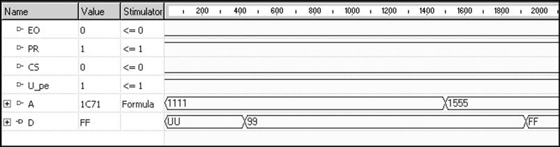
Рис. 15. Эпюры работы ППЗУ D2764A.
4. Описание схемы
Ниже дано описание схемы на языке VHDL.
library IEEE;
use IEEE.std_logic_1164.all;
Entity Main is
port(
CUST_01: in STD_LOGIC;
CUST_02: in STD_LOGIC;
OUT_01: out STD_LOGIC_VECTOR(3 downto 0);
OUT_02: out STD_LOGIC_VECTOR(3 downto 0)
);
End Main;
Architecture Main_ARCHITECTURE of Main is
component CT2
port(
R: in STD_LOGIC;
PE: in STD_LOGIC;
C_U: in STD_LOGIC;
C_D: in STD_LOGIC;
D: in STD_LOGIC_VECTOR (3 downto 0);
Q: out STD_LOGIC_VECTOR (3 downto 0);
TC_U: out STD_LOGIC
);
end component;
component RG
port(
C: in STD_LOGIC;
EW: in STD_LOGIC;
D: in STD_LOGIC_VECTOR (7 downto 0);
O: out STD_LOGIC_VECTOR (7 downto 0)
);
end component;
component MS
port(
SED: in STD_LOGIC;
EZ: in STD_LOGIC;
D0: in STD_LOGIC_VECTOR(3 downto 0);
D1: in STD_LOGIC_VECTOR(3 downto 0);
MS: out STD_LOGIC_VECTOR(3 downto 0)
);
end component;
component ROM
port(
A: in STD_LOGIC_VECTOR (12 downto 0);
CS: in STD_LOGIC;
EO: in STD_LOGIC;
PR: in STD_LOGIC;
U_pe: in STD_LOGIC;
D: out STD_LOGIC_VECTOR (7 downto 0)
);
end component;
signal SW_02: STD_LOGIC := '1';
signal SW_03: STD_LOGIC := '1';
Уважаемый посетитель!
Чтобы распечатать файл, скачайте его (в формате Word).
Ссылка на скачивание - внизу страницы.